Figure 23. cpu fan location, 23 cpu fan location – Intel Core 2 Duo User Manual
Page 31
Intel
®
Core
TM
2 Duo Processor and Intel
®
Q35 Express Chipset Development Kit
October 2007
User’s Manual
Order Number: 318476001US
31
Setting Up and Configuring the Development Kit—Intel Core 2 Duo Processor and Intel Q35
Express Chipset
2. Set jumpers to default positions. Refer to
for default positions.
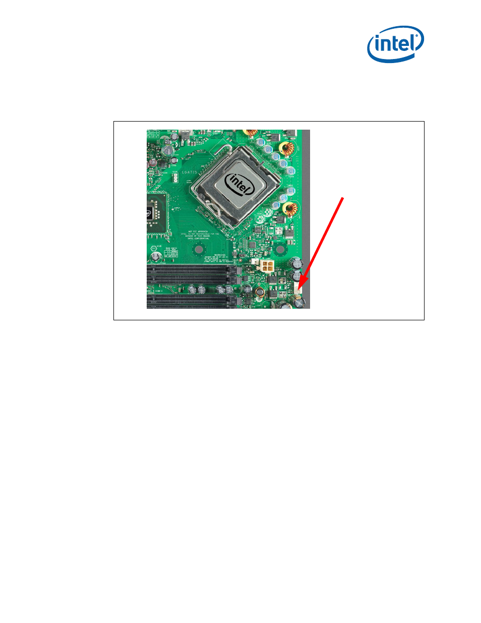
3. Install the processor and ensure the 4-pin CPU fan power connector is installed on
header shown in
4. Install the DDR2 DIMM in the Channel A Slot 0 connector. DIMMs should never be
inserted or removed unless the power supply is disconnected from the AC power
for system memory configuration.
5. Connect a SATA hard drive, USB keyboard, USB mouse, and VGA monitor (video
card is optional).
6. Connect a 2x12 standard power supply and 2x2 standard power supply as well.
for the location.
7. Plug the power cable into the back of the power supply, leaving the switch in the
OFF position.
8. Once the board is set up, plug the cord into the power source. Switch on the power
supply.
9. Press the power button. Refer to
or
for power-on button
location.
Figure 23.
CPU Fan location
4-pin CPU Fan Power