2 rj-45 lan connector with integrated leds, Figure 10. lan connector led locations, Table 8. lan connector led status – Intel Core 2 Duo User Manual
Page 19: 3 usb port, 4 coaxial s/pdif in/out connector, 5 esata port, Rj-45 lan connector with integrated leds, Usb port, Coaxial s/pdif in/out connector, Esata port
Intel
®
Core
TM
2 Duo Processor and Intel
®
Q35 Express Chipset Development Kit
October 2007
User’s Manual
Order Number: 318476001US
19
Development Kit Hardware Features—Intel Core 2 Duo Processor and Intel Q35 Express Chipset
Center/Subwoofer Speaker Out Jack (Orange)
This audio jack is used to connect to center/subwoofer speakers in a 5.1 and 7.1-
channel audio configuration.
Rear Speaker Out (Black)
This audio jack is used to connect to rear speakers in a 5.1 and 7.1-channel audio
configuration.
Side Speaker Out (Gray)
This audio jack is used to connect to side speakers for 7.1-channel audio configuration
only.
2.6.2
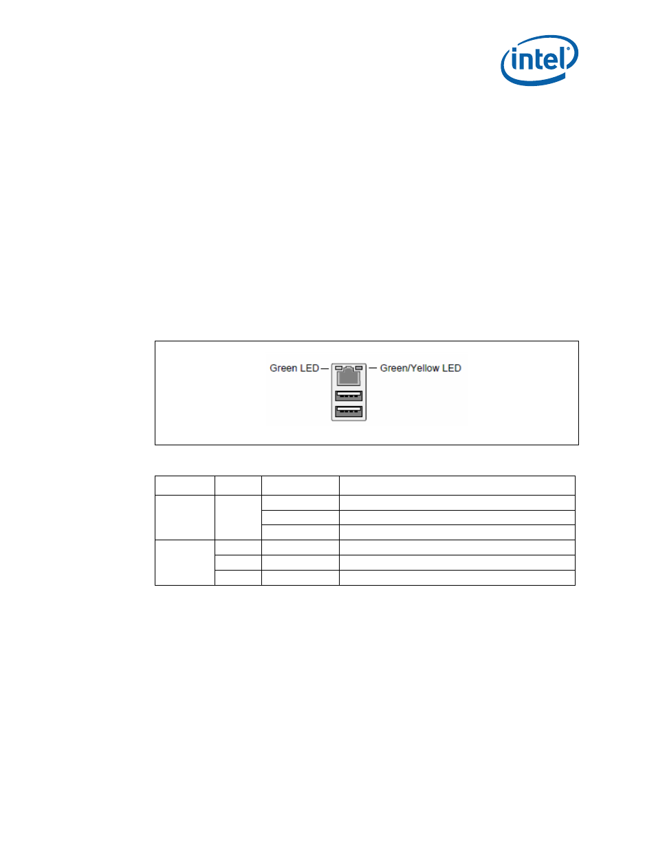
RJ-45 LAN Connector with Integrated LEDs
Two LEDs are built into the RJ-45 LAN connector (as shown in
describes the LED states when the board is powered up and the Gigabit LAN subsystem
is operating.
2.6.3
USB Port
The USB port supports the USB 1.1/2.0 specification.
2.6.4
Coaxial S/PDIF In/Out Connector
This connector provides digital audio input and output from external audio system that
supports digital coaxial audio. Ensure that the audio system provides a coaxial digital-
in/out connector.
2.6.5
eSATA Port
This development kits support the first generation eSATA port.
Figure 10.
LAN Connector LED locations
Table 8.
LAN Connector LED status
LED
Color
LED State
Condition
Left
Green
Off
LAN link is not established
On
LAN link is established
Blinking
LAN activity is occurring
Right
N/A
Off
10 Mbits/sec data rate is selected
Green
On
100 Mbits/sec data rate is selected
Yellow
On
1000 Mbits/sec data rate is selected