1 jumper functions, 2 usb 2.0 front panel, Table 11. usb front panel – Intel Core 2 Duo User Manual
Page 22: 3 1394a header, Jumper functions, Usb 2.0 front panel, 1394a header, 10 intel, Core, 2 duo processor and intel
Intel Core 2 Duo Processor and Intel Q35 Express Chipset—Development Kit Hardware Features
Intel
®
Core
TM
2 Duo Processor and Intel
®
Q35 Express Chipset Development Kit
User’s Manual
October 2007
22
Order Number: 318476001US
2.8.1
Jumper Functions
provides a list of the setting definitions for the Intel
®
Core
TM
2 Duo Processor
and Intel
®
Q35 Express Chipset Development Kit.
2.8.2
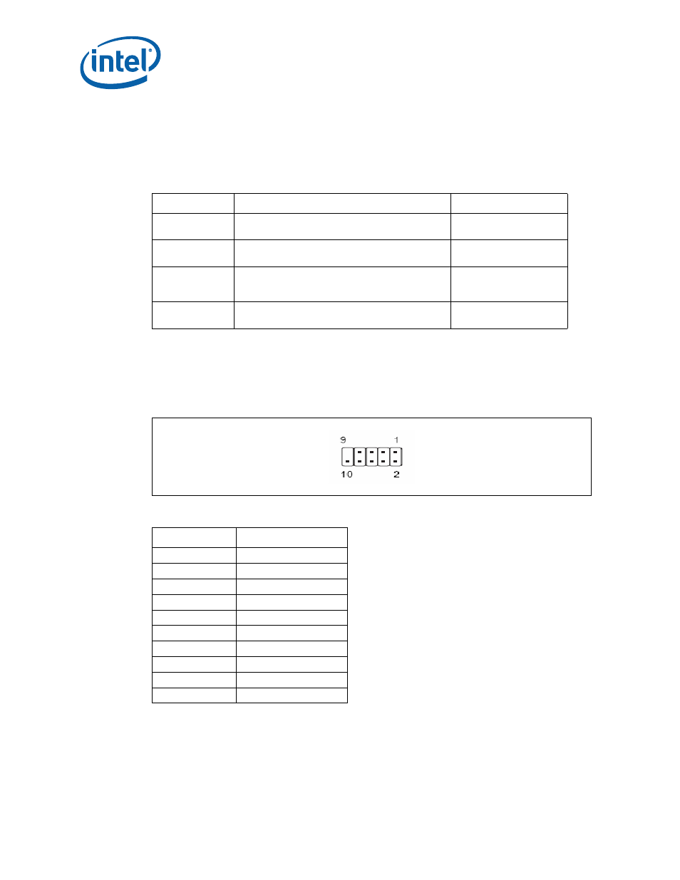
USB 2.0 Front Panel
There are 4 USB 2.0 Front Panel can be found in the development kits board. Front
panel USB header thermistor protection is required. USB front panel is label as U14LB,
U15LB, U16LB and U1FW on the boards. Refer to
for header location of
U14LB, U15LB and U16LB. Refer to
for U1FW.
2.8.3
1394a Header
The development kit board supports a 1394a solution on the PCIe bus with a single
1394a port on the back panel (see
) and another header supporting a 1394a
). Front panel 1394a header thermistor protection is required.
Table 10.
Intel
®
Core
TM
2 Duo Processor and Intel
®
Q35 Express Chipset Development
Kit Board Jumpers Description
Jumper
Description
Default Position
J6LB
Clear CMOS
(1-2: Normal, 2-3: Clear CMOS)
1-2
J115LB
RTC Reset
(1-2: Normal, 2-3: Clear)
1-2
J7LB
Config /Recovery
(1-2: Normal, 2-3: Configure, jumper removed –
recovery)
1-2
J4LB/J10LB
Manufacturing mode
(enable if jumper plug-in)
Empty
Table 11.
USB Front Panel
Pin Number
Definition
1
5V
2
5V
3
USB Dx-
4
USB Dy-
5
USB Dx+
6
USB Dy+
7
GND
8
GND
9
No pin
10
No connect