4 board setup and configuration before boot, Board setup and configuration before boot, 22 tightening heatsink on the srm and board – Intel Core 2 Duo User Manual
Page 30: Figure 22
Intel Core 2 Duo Processor and Intel Q35 Express Chipset—Setting Up and Configuring the
Development Kit
Intel
®
Core
TM
2 Duo Processor and Intel
®
Q35 Express Chipset Development Kit
User’s Manual
October 2007
30
Order Number: 318476001US
3.4
Board Setup and Configuration before Boot
Follow the steps below to operate the board.
Warning:
Before starting, ensure the power supply is not connected to the board.
Ensure a safe and static-free work environment before removing any components from
their anti-static packaging. The Development Platform is susceptible to electrostatic
discharge, which may cause failure or unpredictable operation.
The Development Platform must be operated on a flame retardant surface because a
chassis is not included with the platform.
Caution:
Connecting the wrong cable or reversing a cable may damage the board and may
damage the device being connected. Since the board is not in a protective chassis, use
caution when connecting cables to the board.
Caution:
The power supply cord is the main disconnect device to main power (AC power). The
socket outlet should be installed near the equipment and should be readily accessible.
To avoid shock, ensure that the power cord is connected to a properly wired and
grounded receptacle. Do not connect/disconnect any cables or perform installation/
maintenance of the boards in this product during an electrical storm. Ensure that any
equipment to which this product will be attached is also connected to properly wired
and grounded receptacles.
Note:
Ensure that setting up the ATX power supply is the final step performed in the process
of assembly.
1. Physically inspect the motherboard for obvious defects. Note that each reference
board has been tested prior to distribution, but a visual check should be performed
to ensure no damage has occurred during shipping.
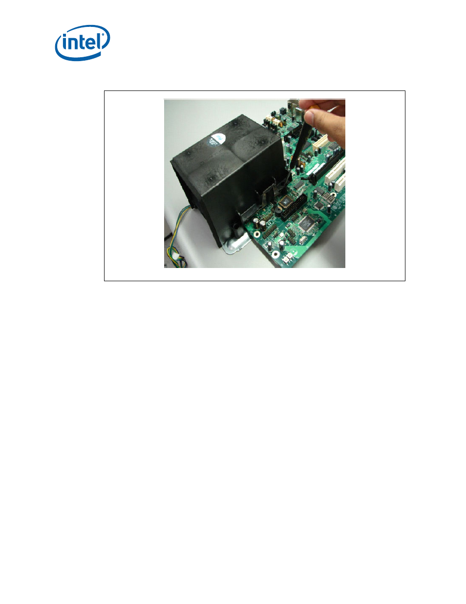
Figure 22.
Tightening Heatsink on the SRM and Board