4 voltage reference, Table 9. voltage reference detail, 8 development kit major connectors and jumpers – Intel Core 2 Duo User Manual
Page 21: Figure 12. major jumper and header locations, Voltage reference, Development kit major connectors and jumpers, 12 major jumper and header locations, Voltage reference detail
Intel
®
Core
TM
2 Duo Processor and Intel
®
Q35 Express Chipset Development Kit
October 2007
User’s Manual
Order Number: 318476001US
21
Development Kit Hardware Features—Intel Core 2 Duo Processor and Intel Q35 Express Chipset
2.7.4
Voltage Reference
See
for details of the expected voltage levels for each voltage rail on the CRB.
2.8
Development Kit Major Connectors and Jumpers
shows major jumpers and headers used on the development kit.
Table 9.
Voltage Reference detail
Voltage Rail
Expected Voltage
Voltage Rail
Expected Voltage
VCC
5.0
V_1P25_CORE
1.25
VCC3
3.3
V_1P25_CL_MCH
1.25
+12V
12
V_1P25_PCIEXPRESS
1.25
-12V
-12
V_SM
1.8
V_5P0_STBY\G
5.0
V_SM_VTT
0.9
V_3P3_STBY\G
3.3
V_3P3_CL
3.3
V_1P5_ICH
1.5
V_3P3_PCIVAUX
3.3
V_1P05_ICH_CORE
1.05
VDD_CLK
3.3
V_FSB_VTT
1.2
VCC_CLK_IO
0.8
VCCP
Varies
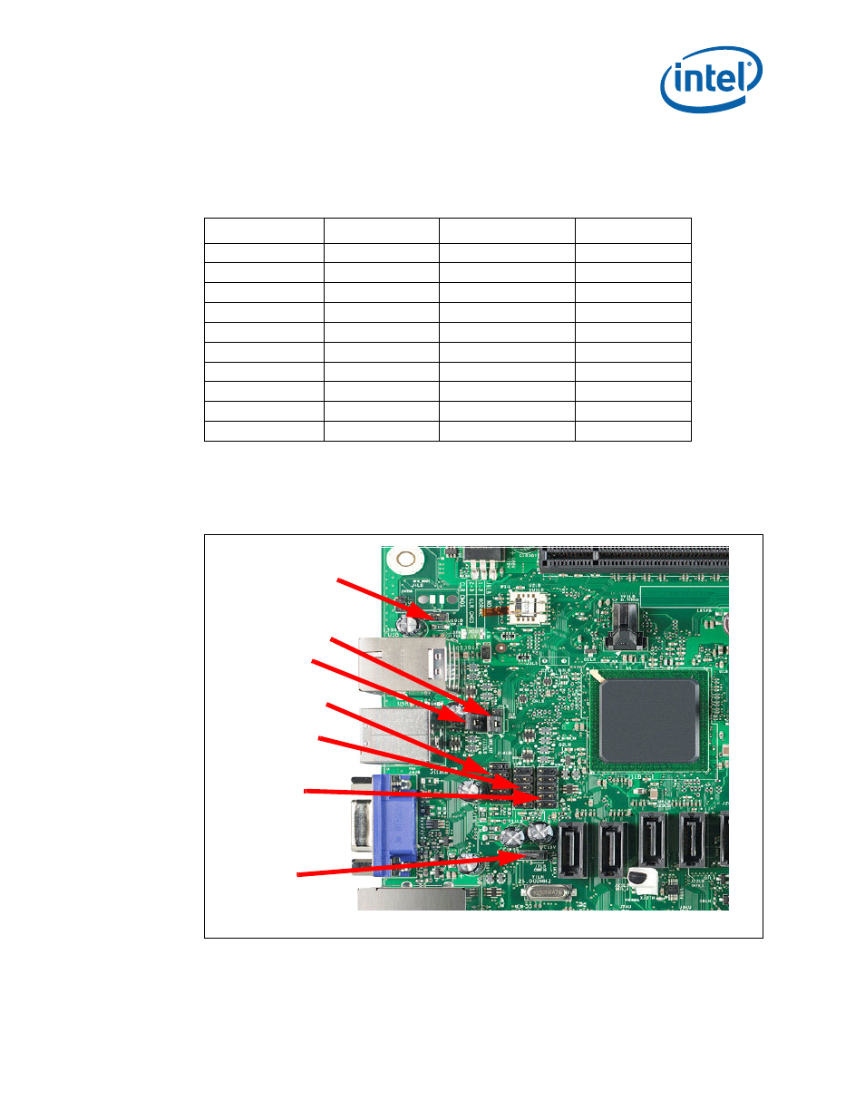
Figure 12.
Major Jumper and Header Locations
J4LB/J10LB
J6LB
J115LB
J14LB
J15LB
J16LB
J7LB