Figure 17. mounting hole locations, 17 mounting hole locations – Intel Core 2 Duo User Manual
Page 27
Intel
®
Core
TM
2 Duo Processor and Intel
®
Q35 Express Chipset Development Kit
October 2007
User’s Manual
Order Number: 318476001US
27
Setting Up and Configuring the Development Kit—Intel Core 2 Duo Processor and Intel Q35
Express Chipset
environment. Since the board is not in a protective chassis, the user is required to
observe extra precautions when handling and operating the system.
The board is a standard uBTX form factor and provides non-plated mounting holes with
top and bottom ground rings. If the board is not going to be used in a chassis,
standoffs are included for bench top use in the lab environment.
The development kit includes eight hex standoffs and for screws to attach to the board
for bench top use. Four of the standoffs are used to mount the heatsink (refer to
for heatsink installation). Attach standoffs to the screws to the board at the
following mounting hole locations.
1. Insert screw through top mounting hole for the BTX Heatsink. Refer to
for
the mounting hole location.
2. Place standoff on backside of board and hand tighten to screw. Refer to
for guide.
3. Repeat for additional standoffs on the board until all standoffs are installed. Refer
to
for recommended mounting hole locations.
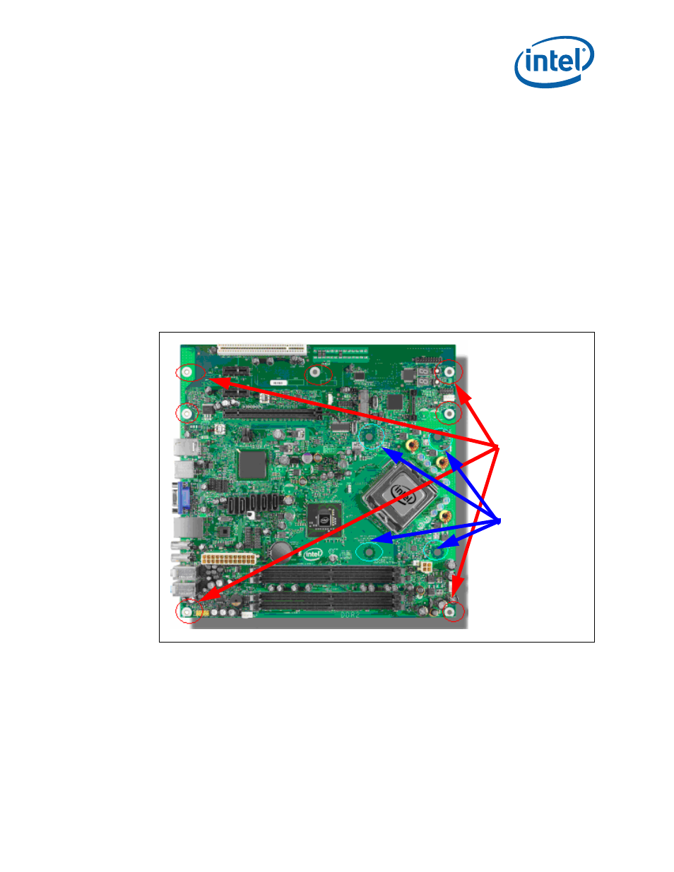
Figure 17.
Mounting Hole Locations
J24LB
Recommended
Mounting Hole
Locations
Mounting Hole for
BTX heatsink
Locations