Table 12. 1394a header, 9 spi removal / installation technique, Spi removal / installation technique – Intel Core 2 Duo User Manual
Page 23: 13 location for 1394a header and usb front panel, 12 1394a header
Intel
®
Core
TM
2 Duo Processor and Intel
®
Q35 Express Chipset Development Kit
October 2007
User’s Manual
Order Number: 318476001US
23
Development Kit Hardware Features—Intel Core 2 Duo Processor and Intel Q35 Express Chipset
2.9
SPI Removal / Installation Technique
When removing or installing the SPI device, care must be taken to avoid damage to the
SPI socket. The cap is constructed of plastic and can easily be damaged.
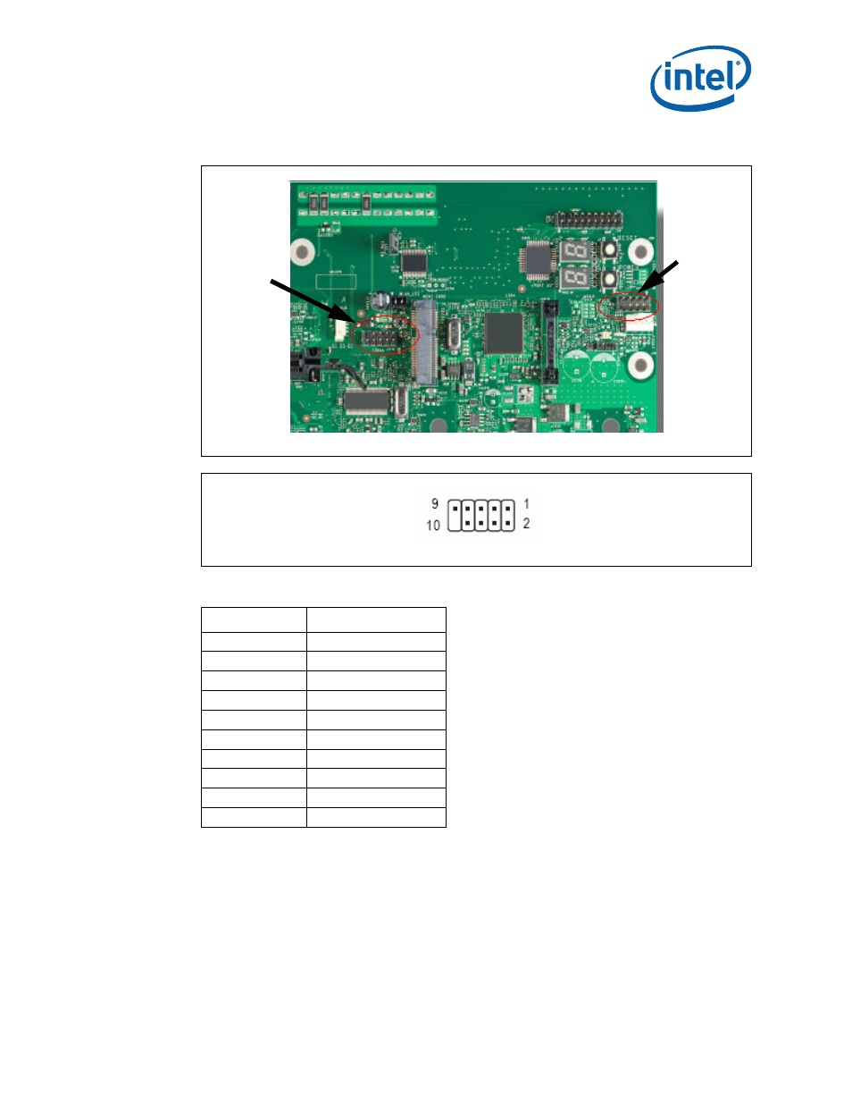
Figure 13.
Location for 1394a Header and USB Front Panel
Table 12.
1394a Header
Pin Number
Definition
1
NDCD A-
2
NSIN A
3
NSOUT A
4
NDTR A-
5
GND
6
NDSR A-
7
NRTS A-
8
NCTS A-
9
NRI A-
10
No Pin
U1FW
(USB Front
Panel)
J24LB
1394a
Header
See also other documents in the category Intel Hardware:
- 41210 (64 pages)
- 8xC251TQ (20 pages)
- ENTERPRISE PRINTING SYSTEM (EPS) 4127 (84 pages)
- U3-1L (20 pages)
- 80960HA (104 pages)
- X58 (54 pages)
- ESM-2850 2047285001R (91 pages)
- ATOM US15W (54 pages)
- D915GVWB (4 pages)
- XP-P5CM-GL (28 pages)
- AX965Q (81 pages)
- CORETM 2 DUO MOBILE 320028-001 (42 pages)
- CV700A (63 pages)
- 80C188EA (50 pages)
- X25-M (28 pages)
- XP-P5IM800GV (26 pages)
- IB868 (60 pages)
- D865GVHZ (88 pages)
- IB865 (64 pages)
- Altera P0424-ND (1 page)
- 8086-2 (30 pages)
- IXDP465 (22 pages)
- IWILL P4D (104 pages)
- GA-8I955X PRO (88 pages)
- FSB400 (PC2100) (96 pages)
- D845GLAD (4 pages)
- NAR-3041 (1 page)
- 87C196CA (136 pages)
- G52-M6734XD (74 pages)
- A96134-002 (10 pages)
- Express Routers 9000 (8 pages)
- 82540EP (45 pages)
- D865GLC (94 pages)
- IB850 (69 pages)
- MB898RF (62 pages)
- Arima LH500 (78 pages)
- V09 (33 pages)
- I/O Processor (22 pages)
- M600 (110 pages)
- SE7520JR2 (63 pages)
- SERVER BOARD S5520HCT (30 pages)
- Extensible Firmware Interface (1084 pages)
- GA-8IPXDR-E (70 pages)
- D845EBG2 (4 pages)
- AW8D (80 pages)