Pci/pci-x interface signals – Intel 41210 User Manual
Page 60
60
Intel® 41210 Serial to Parallel PCI Bridge Design Guide
Design Guide Checklist
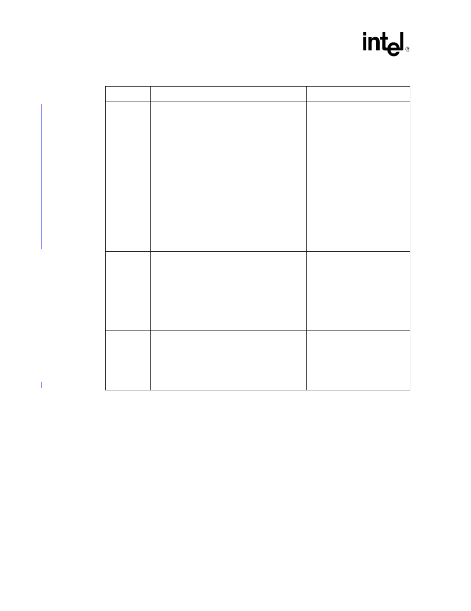
Table 20. PCI/PCI-X Interface Signals
Signals
Recommendations
Reason/Impact
X_AD[63:32]
X_CBE[7:4]#
X_DEVSEL#
X_FRAME#
X_IRDY#
X_TRDY#
X_STOP#
X_PERR#
X_SERR#
X_REQ[5:0]#
X_GNT[5:0]#
X_LOCK#
X_PAR
X_PAR64
X_ACK64#
X_REQ64#
No external pullup resistors required on system board.
41210 Bridge has internal pullup
resistors on these signals.
X_AD[31:0] and X_CBE#[3:0]
signals do not require pullups
according to the PCI Specification.
A_133EN
B_133EN
Only relevant when running in PCI-X Mode
(X_PCIXCAP = 1).
Determines the max PCI-X Mode 1 frequency for a
particular segment (100 MHz or 133 MHz):
0 = 100 MHz PCI-X max frequency
1 = 133 MHz PCI-X max frequency
Use an 8.2K
Ω
pullup resistor to VCC33. This resistor is
located on the system board.
Sampled on the rising edge of
PERST#.
A_INTA#,
A_INTB#,
A_INTC#,
A_INTD#,
B_INTA#,
B_INTB#,
B_INTC#,
B_INTD#
No pullup resistors required on these signals.
The 41210 Bridge has internal
pullup resistors on these signals.