Circuit implementations 10, 1 41210 bridge analog voltage filters, Circuit implementations – Intel 41210 User Manual
Page 49: 41210 bridge analog voltage filters
Intel® 41210 Serial to Parallel PCI Bridge Design Guide
49
Circuit Implementations
10
This chapter describes 41210 Bridge circuit implementations.
10.1
41210 Bridge Analog Voltage Filters
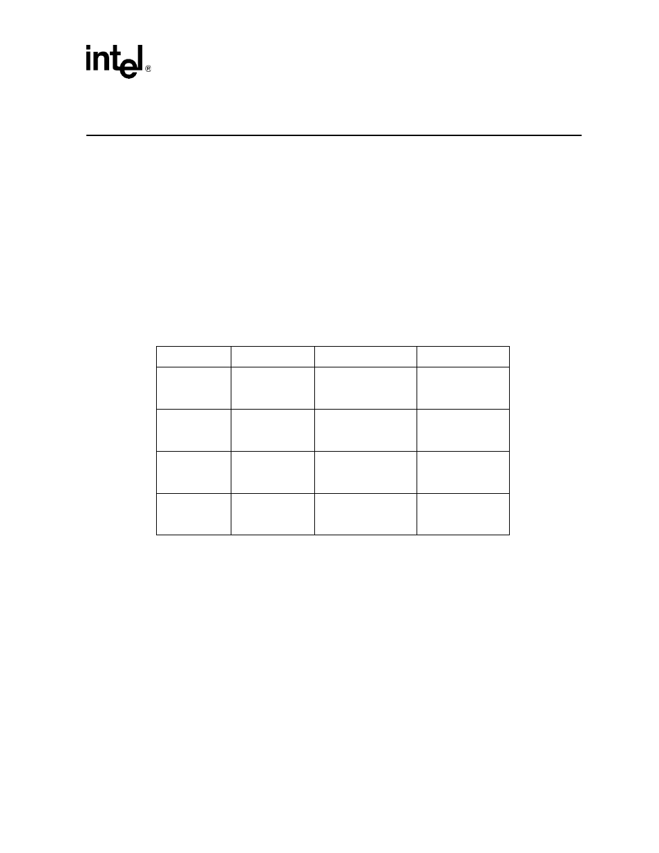
The Intel® 41210 Serial to Parallel PCI Bridge requires several external analog voltage filter
circuits to be placed on the system board, three for the PCI interface, one for the PCI Express
interface, and one for the bandgap voltage. The 41210 Bridge lists the recommended filter values
for these filter circuits -- any one of the filter circuits can use any one of the four R, L and C
combinations shown in
, except that configuration number 4 cannot be used for the PCI
Express analog voltage filter.
Table 16.
Recommended R, L and C Values for 41210 Bridge Analog Filter Circuits
Additional notes:
L (Inductor)
— L must be magnetically shielded
— ESR: max < 0.4
Ω
— rated at 45mA (or 30mA for bandgap circuit only)
C (Capacitor)
— ESR: max < 0.5
Ω
— ESL < 3.0nH
R (Resistor)
— 1/16W
Config
R
L
C
1
0.5
Ω
±1%
1/16W
4.7uH ±25%
PCI, PCI-E: 45mA
Bandgap: 30mA
33uF ±20%
6.3V
2
0.5
Ω
±1%
1/16W
4.7uH ±20
PCI, PCI-E: 45mA
Bandgap: 30mA%
22uF ±20%
6.3V
3
0.5
Ω
±1%
1/16W
4.7uH ±20%
PCI, PCI-E: 45mA
Bandgap: 30mA
2x10uF ±20%
6.3V
4
a
a.
Configuration number 4 cannot be used for the PCI Express analog voltage filter.
1.0
Ω
±1%
1/16W
4.7uH ±20%
PCI: 45mA
Bandgap: 30mA
10uF ±20%
6.3V