Use page 2 – Marantz SR8002 User Manual
Page 56
ENGLISH
53
4 VIDEO SETUP
Video settings are made as follows.
1.
Select “4. VIDEO SETUP” from the MAIN
MENU with the
3/4 cursor buttons and press
the OK/ENTER button.
4 . V I D E O S E T U P
V I D E O C O N V E R T
T V . A U T O : D I S A B L E
O S D I N F O : E N A B L E
I / P C O N V E R T : E N A B L E
H D M I O U T : O U T P U T 1
C O M P O O U T 2 : M A I N
R E T U R N
N E X T
E X I T
2.
Select the desired menu with the
3/4 cursor
buttons and press the OK/ENTER button.
• VIDEO CONVERT
“4-1 VIDEO CONVERT”
• TV-AUTO
Select the TV AUTO ON/OFF function to enable
or disable with the
1 or 2 cursor buttons. (refer to
page 66)
• OSD INFO
Select the OSD information function to “ENABLE”
or “DISABLE” with the
1 or 2 cursor buttons.
If you select “ENABLE”, this unit will display the
status of the feature (Volume up/down, input
select, etc..) on the monitor. If you do not desire
this information, select “DISABLE”.
Note:
• OSD information is not output to Monitor Output
of HDMI and Component Video. However, OSD
information is output if the Video Convert function
is used to output Video or S-Video video signals to
Monitor Out of HDMI and Component Video.
For details, refer to“VIDEO CONVERT”on page 59.
• IP CONVERT
Select the IP CONVERT ON/OFF function to
enable or disable with the
1 or 2 cursor buttons.
(refer to page 59)
• HDMI OUT
This setting is for selecting which output terminal,
HDMI 1 or HDMI 2, to output the signal to. Select
the output destination with the
1 / 2 cursor
buttons.
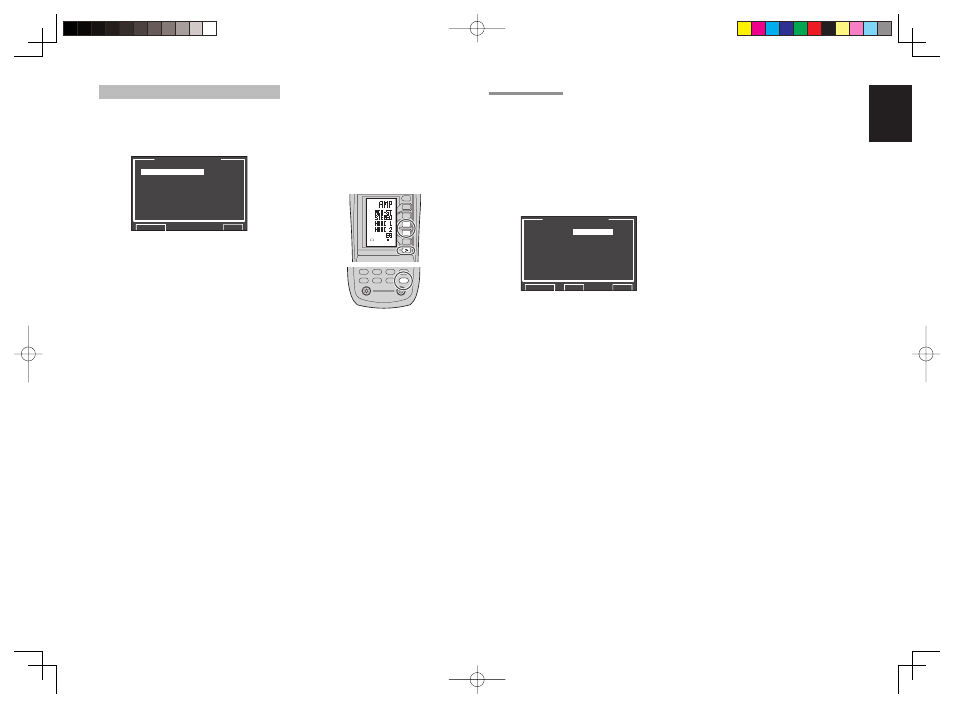
To use the remote controller (RC8001SR) to
change the HDMI OUT setting, press the AMP
button and then the > button until the second page
is displayed. After HDMI 1 or HDMI 2 is displayed
on the remote controller, press the D3 or D4 button
to switch between them.
AMP
AUX2
AUX1
TAPE
TUNER
CD
CD-R
MD
1
2
LIGHT
Learning Remote Controller
RC8001SR
AMP
D4
D5
D2
M
D1
D3
D5
VOL
CH
USE
PAGE
2
D4
D3
• COMPONENT OUT 2
(This feature is not available on the SR7002.)
This setting is for selecting whether to output
the images for the main room or the images for
the multi room system to the COMPONENT
MONITOR OUT 2 terminal. Select the output
destination between MAIN and MULTI with the
1 /
2 cursor buttons.
Note:
• When MULTI is selected, video signals converted
from the MONITOR OUT 2 terminal are not
output.
After you complete this portion of the setup, move
cursor to “RETURN” with the
3, 4, 1 and 2 cursor
buttons and press the OK/ENTER button.
4-1 VIDEO CONVERT
This unit is equipped to convert video signals for
monitor output.
This section explains how to set up conversion for
each type of video input.
1.
Select “4. VIDEO SETUP” from the MAIN
MENU with the
3 / 4 cursor buttons and press
the OK/ENTER button.
2.
Select “VIDEO CONVERT” with the
3 / 4 cursor
buttons and press the OK/ENTER button.
V I D E O C O N V E R T
T V :
A N A & H D M I
D V D : A N A & H D M I
V C R 1 : A N A & H D M I
D S S : A N A & H D M I
A U X 1 : A N A & H D M I
T A P E : A N A & H D M I
C D / R : A N A & H D M I
A U X 2 : A N A & H D M I
R E T U R N B A C K
E X I T
3.
Select “FUNCTION” with the
3 / 4 cursor
buttons and set the video conversion mode
with the
1 / 2 cursor buttons
ANA&HDMI:
This mode both up-converts and down-converts
analog video signals (Composite Video, S-Video,
Component Video). Furthermore, it up-converts
from analog video signal to HDMI. (It cannot down-
convert from HDMI digital video signals to analog
video signals.)
ANA ONLY:
This mode both up-converts and down-converts
analog video signals (Composite Video, S-Video,
Component Video). It does not up-convert to
HDMI.
OFF:
This mode turns off all conversion features.
Note:
• For details on video convert feature, see page 59.