Optional fan/blower system (blotbldvsc) – Monessen Hearth WIDEVIEW WDV500 User Manual
Page 25
78D0011
25
WDV Series Gas Fireplace
sIGnature cOMManD - OptIOnal Fan BlOWer systeM
a/c WIrInG tO junctIOn BOx
IMpOrtant: always check local building codes.
this installation must comply with local regulations
as well as the national electric code.
WIrInG
1. Before installing the blower, wire the receptacle into an
electrical circuit. This should be done before framing the
fireplace. Wire with minimum 60° C wire in accordance
with prevailing codes.
2. Remove the external junction box cover by removing
the screw from the right side of the outside firebox wall.
Junction box was installed at the factory.
3. The junction box cover has a factory installed “romex”
style strain relief connector. After connecting the wires,
route the wire leads through this connector. Refer to the
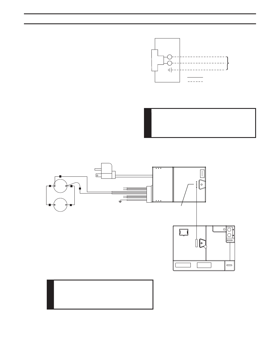
wiring diagram in Figure 33.
FP1912
Junction box wiring
8/08
120V AC
60Hz
Factory Supplied
Not Supplied
junction Box
Figure 33 -
Junction Box Wiring Diagram
W
a
rn
In
G
Before installing the blower, turn off the fireplace and
allow to cool. Only a qualified service person should
service and repair the fireplace. A qualified service
person should connect and disconnect the fireplace
to gas supply. Follow all local codes.
To Junction Box
In Fireplace
White
Black
White
Black
Black
White
Green
Connector
Pin To Control Box
AC Module
{
{
Light
Control Box
Blower
Right
Blower
Left
Black
Black
FP1915
AC box wiring
8/08
AUX
Figure 34 -
Blower Wiring Diagram
FP1915
W
a
rn
In
G
Electrical Grounding Instructions: This appli-
ance is equipped with a three-prong (grounding)
plug for your protection against shock hazard
and should be plugged directly into a properly
grounded three prong receptacle.
OptIOnal Fan/BlOWer systeM (BlOtBlDVsc)