Front panel connector: jfp1, Front panel audio connector: jaud1, Important – MSI FUZZY 945GME1 User Manual
Page 31
2-13
Hardware Setup
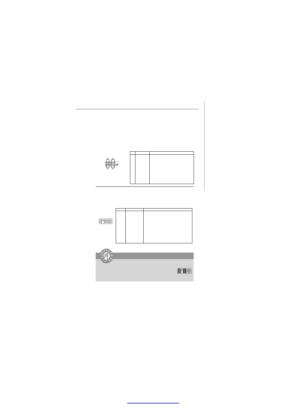
Front Panel Connector: JFP1
The mainboard provides one front panel connector for you to connect to the
front panel switches and LEDs. JFP1 is compliant with Intel
®
Front Panel I/O
Connectivity Design Guide.
Front Panel Audio Connector: JAUD1
This connector allows you to connect the front panel audio and is compliant
with Intel
®
Front Panel I/O Connectivity Design Guide.
Pin Definition
PIN
1
2
3
4
5
6
7
8
9
10
SIGNAL
N/C
AUD_GND
AUD_MIC
AUD_VCC
AUD_FPOUT_R
AUD_RET_R
N/C
KEY
AUD_FPOUT_L
AUD_RET_L
DESCRIPTION
N/C
Ground used by analog audio circuits
Microphone power
Filtered +5V used by analog audio circuits
Right channel audio signal to front panel
Right channel audio signal return from front panel
N/C
No pin
Left channel audio signal to front panel
Left channel audio signal return from front panel
1
2
JAUD1
9
10
Important
If you don
’t want to connect to the front audio header, pins
5 & 6, 9 & 10 have to be jumpered in order to have signal
output directed to the rear audio ports. Otherwise, the
Line-Out connector on the back panel will not function.
5
9
6
10
PIN
1
2
3
4
5
6
7
8
9
Pin Definition
SIGNAL
HD_LED_P
FP PWR/SLP
HD_LED_N
FP PWR/SLP
RST_SW_N
PWR_SW_P
RST_SW_P
PWR_SW_N
RSVD_DNU
DESCRIPTION
Hard disk LED pull-up
MSG LED pull-up
Hard disk active LED
MSG LED pull-up
Reset Switch low reference pull-down to GND
Power Switch high reference pull-up
Reset Switch high reference pull-up
Power Switch low reference pull-down to GND
Reserved. Do not use.
JFP1
2
1
10
9
HDD
LED
Reset
Switch
Power
LED
Power
Switch
+ -
+ -
- +
PDF created with pdfFactory Pro trial versi