Galaxy 4000 – MGE UPS Systems 40-75KVA User Manual
Page 24
CAUTION
Isolate and lock-out all power sources for this card before making connections.
Never connect ELSV (extra low safety voltage) and non-ELSV circuits to the
different outputs of the same card.
2.4.1
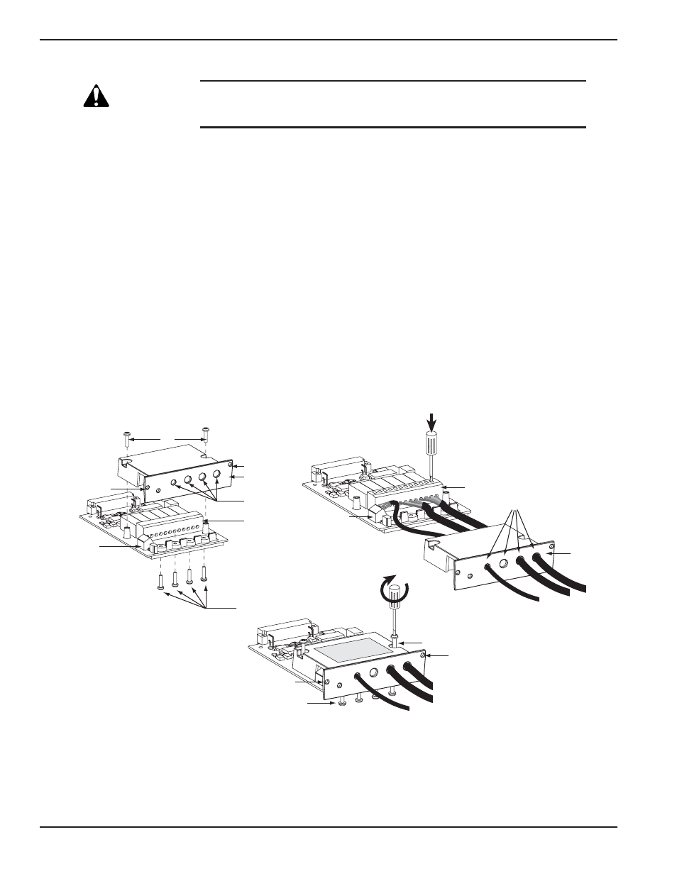
Relay Communication Card Connections
Refer to Figure 2-3 for relay communication card, cover and hardware details. See Figure 4-1 for communication
card port location in the unit.
1.
Remove the cover “3” secured by the screws “1”.
2.
Run the communication cables through the cable entry holes “4”.
3.
Connect the conductors to the input “6” and output “5” terminal blocks (refer to Figure 2-3 for a
connection example.)
4.
Put the cover back in place and secure it with the screws “1”.
5.
Tighten the screws “7” to clamp the cables.
6.
Indicate the locations of the power sources on the labels.
7.
Insert the card in its slot.
8.
Secure the card with two screws “2”.
Figure 2-3: Relay Communication Card.
1
2 3
4 5
6
A
B
1 2 3
4 5 6
A
B
4
3
5
6
1
2
2
7
1
2
3
2
5
7
6
4
Revmove Cover
Replace Cover
Galaxy 4000
Installation
2 — 6
86-173010-00 A00