Galaxy 4000 – MGE UPS Systems 40-75KVA User Manual
Page 16
Galaxy 4000
1 — 4
86-173010-00 A00
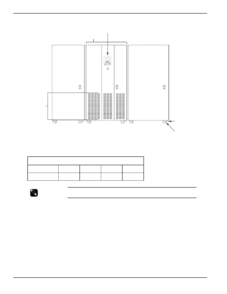
Figure 1-3: Cabinet Placement, Airflow and Recommended Clearances.
Table 1-1: Heat Rejection Data.
NOTE:
To provide for adequate ventilation, a minimum of 36 inches clearance should
be maintained above the top of the Galaxy 4000 cabinet.
1.8
Cabinet Clearances
The Galaxy 4000 UPS cabinet top clearance of 36 inches for fan exhaust is recommended. Additionally, adequate
space must be included in the front and top of each cabinet (approx. 36 inches) to allow the doors/panels of the
cabinet to be opened for service and maintenance procedures.
For an installation where seismic requirements must be met, additional clearance at the side of the cabinet must be
included to accommodate the seismic anchors. Contact your local MGE Sales Representative to order. See Figure 1-4.
1.9
Conduit Plate Locations for Bottom Entry
Cable entry through the bottom is the standard preferred design for the Galaxy 4000 UPS cabinet. The bottom entry
conduit plate provides space for up to five (5) separate conduit entries. The plate is secured with screws which
should be retained for the conduit plate after the power connections are made. See Figure 1-4 for the location of
the bottom entry conduit plates.
Heat Rejection Data @ 208/208VAC
UPS cabinet
40KVA
50KVA
65KVA
75KVA
BTU/Hr
14,900
18,700
24,200
28,000
ALLOW 36" TOP CLEARANCE
FOR FAN EXHAUST AND SERVICE MAINTENANCE
AIR EXHAUST
DISPLAY PANEL
LEVELING
JACKS
CASTERS
UPS CABINET
Galaxy 4000
EXTERNAL BATTERY
CABINET
(Optional)
FRONT VIEW
?
!
!
2
3
4
1
(
(
DISTRIBUTION
CABINET
(Optional)
AIR INTAKE
Introduction