Installation and user manual – MGE UPS Systems 40-75KVA User Manual
Page 23
Installation and User Manual
2.3.8
External Maintenance Bypass Control Connections (optional)
The external maintenance bypass (MBP) control connections are made with the MBP control cable from the external
MBP to the UPS terminal block TB4-9 to TB4-10. See Figure 2-1.
ELECTRICAL
These wires carry HIGH VOLTAGE 120VAC.
2.3.9
Accessories Outlets
The 120VAC outlets to be used on MGE authorized accessories only. The outlets total current not to exceed 2 amps.
CAUTION
Improper use of outlets may cause failure or damage to UPS.
2.4
Relay Communication Card Contacts
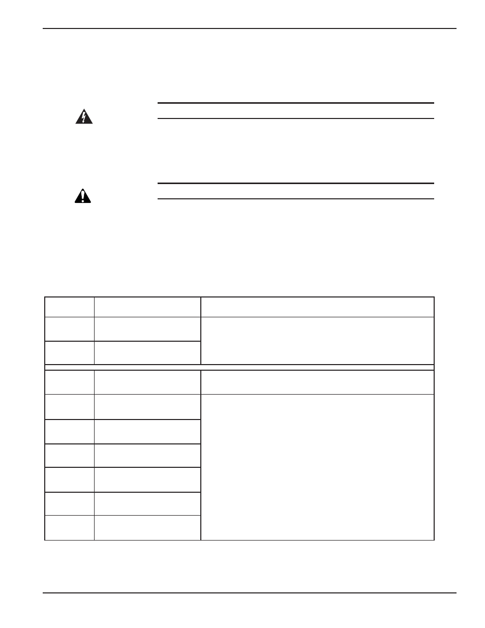
The relay communication card contains six programmable dry contact outputs and two programmable dry inputs
and is standard on the Galaxy 4000. The inputs and outputs are factory programmed according to functions listed
in Table 2-2.
Table 2-2: Relay Contacts (communication card).
The output contacts numbers for a second relay board installed will be 2.1 to 2.6. Contacts are of the NO
(normally open) type. For dry contacts setting see section 3.7
INPUTS
Factory Settings
Options (available on both contacts)
1.A
UPS ON
-Room temperature fault.
-Transfer to bypass disabled.
-Transfer to bypass disabled if bypass AC source out of tolerance.
-Desynchronize UPS from bypass AC source.
1.B
UPS OFF
OUTPUTS
Factory Settings
Options (available on all contacts)
1.1
General alarm
-Overload.
-PFC Fault.
-Inverter fault.
-Charger fault.
-Automatic bypass fault.
-Bypass AC source out of tolerance.
-Battery-temperature fault.
-Emergency power off activated.
-Battery circuit breaker(s) open.
-Phase-sequence fault on normal or bypass.
-AC source.
-Blown fuse(s).
-Transfer to bypass AC source disabled.
-Operation in ECO mode.
-UPS on bypass AC source.
1.2
Battery fault
1.3
Load on UPS
1.4
Load on automatic bypass
1.5
Load on battery power
1.6
Low battery warning
Installation
2 — 5
86-173010-00 A00