Marathon monitors inc – Marathon Computer AACC 2000 User Manual
Page 83
Marathon Monitors Inc.
AACC 2000 Carbon Nov. 1, 1997
83
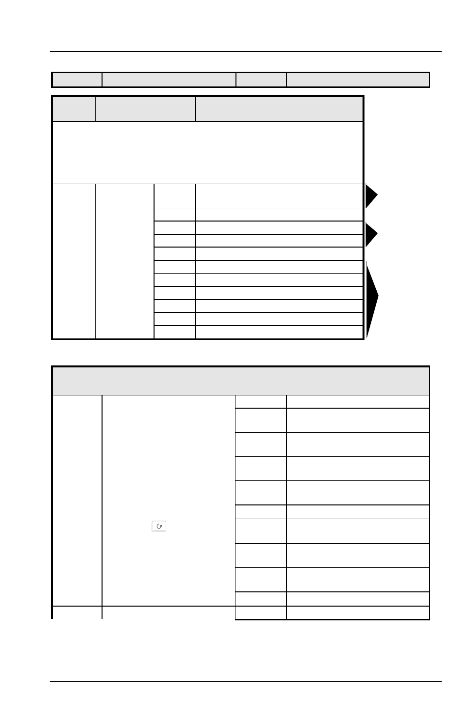
Name
Description
Values
Meaning
CAL
CAL
Calibration
In this mode you can
1. Calibrate the instrument using a mV source -
rcAL or ref source cal.
2. Offset the calibration to account for errors in actual sensor
measurement and a ref sensor -
UCAL or user calibration
3. Return to factory set calibration -
FACT or factory set calibration.
rcAL
Calibration
point
nonE
No calibration
PV
Calibrate main Process Value input.
PV.2
Calibrate DC input, or PV 2.
1A.Hi
Calibrate DC output high - Module 1
1A.Lo
Calibrate DC output low - Module 1
2A.Hi
Calibrate DC output high - Module 2
2A.Lo
Calibrate DC output low - Module 2
3A.Hi
Calibrate DC output high - Module 3
3A.Lo
Calibrate DC output low - Module 3
I
NPUT
C
ALIBRATION
For ‘
CAL
’ = ‘
PV’, or ‘PV.2
’, the following parameters apply.
PV
PV Calibration Value
IdLE
Idle
mv.L
Select 0mV as the calibration
point
mv.H
Select 50mV as the calibration
point
V 0
Select 0Volt as the calibration
point
1. Select calibration value
V 10
Select 10V as the calibration
point
2. Apply specified input
CJC
Select 0
o
C CJC calibration point
3. Press
to step to ‘
GO’
rtd
Select 400
Ω
as the calibration
point
HI 0
High impedance: 0Volt cal’n
point
HI 1.0
High impedance: 1.0 Volt cal’n
point
See Note below.
FACt
Restore factory calibration
GO
Start calibration
no
Waiting to calibrate PV point
Goto User
calibration
table-See also
chapter 7
Go to input
Calibation table
Go to
DC Output
Calibration
table