Marathon monitors inc – Marathon Computer AACC 2000 User Manual
Page 40
Marathon Monitors Inc.
AACC 2000 Carbon Nov. 1, 1997
40
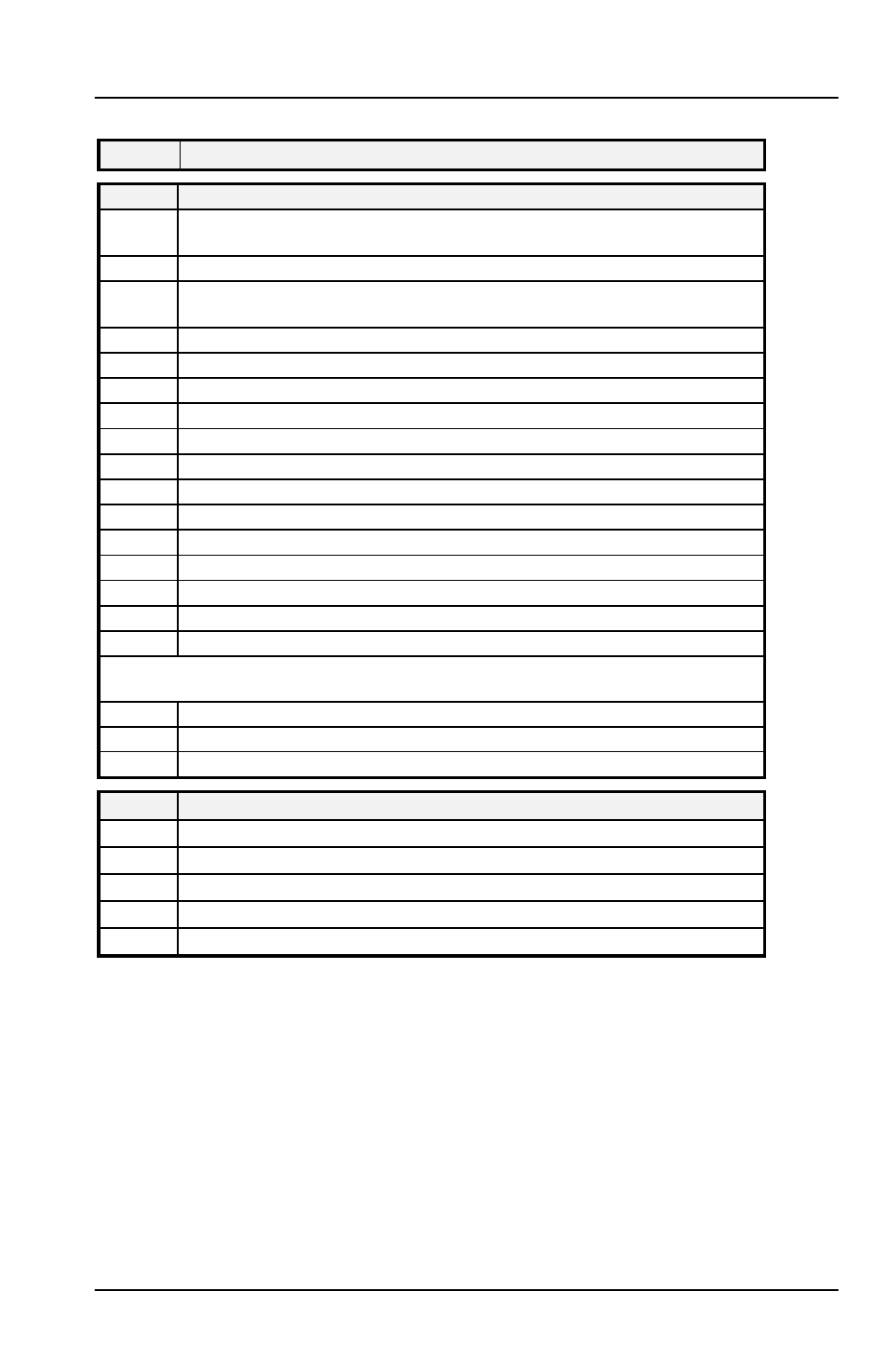
Name
Description
Pid
Pid
PID list
G.SP
G.SP
If Gain Scheduling has been enabled (see Chapter 4), this parameter sets
the PV below which ‘
Pid.1’ is active and above which ‘Pid.2’ is active.
SEt
SEt
‘
Pid.1’ or ‘Pid.2’ selected
Pb
Pb
Proportional Band
(
SEt 1)
(in display units)
ti
ti
Integral Time in secs(
SEt 1)
td
td
Derivative Time in secs
(
SEt 1)
rES
rES
Manual Reset (%)
(
SEt 1)
Hcb
Hcb
Cutback High
(
SEt 1)
Lcb
Lcb
Cutback Low
(
SEt 1)
rEL.C
rEL.C
Relative Cool Gain
(
SEt 1)
Pb2
Pb2
Proportional Band
(
SEt 2)
ti2
ti2
Integral Time in secs(
SEt 2)
td2
td2
Derivative Time in secs
(
SEt 2)
rES.2
rES.2
Manual Reset (%)
(
SEt 2)
Hcb2
Hcb2
Cutback High
(
SEt 2)
Lcb2
Lcb2
Cutback Low
(
SEt 2)
rEL.2
rEL.2
Relative Cool Gain
(
SEt 2)
The following three parameters are used for cascade control. If this facility is not
being used, then they can be ignored.
FF.Pb
FF.Pb
SP, or PV, feedforward propband
FF.tr
FF.tr
Feedforward trim %
FF.dv
FF.dv
PID feedforward limits
±
%
mtr
mtr
Motor list - see Table 4-3
tm
Valve travel time in seconds
In.t
Valve inertia time in secs
bAc.t
Valve backlash time in secs
mp.t
Minimum ON time of output pulse
U.br
Valve sensor break strategy