Hdv series direct vent gas fireplace, Fp2103 ac fan wiring, Optional fan blower system – Monessen Hearth HDV500NV/PV User Manual
Page 36: Warning
HDV Series Direct Vent Gas Fireplace
36
56D3048
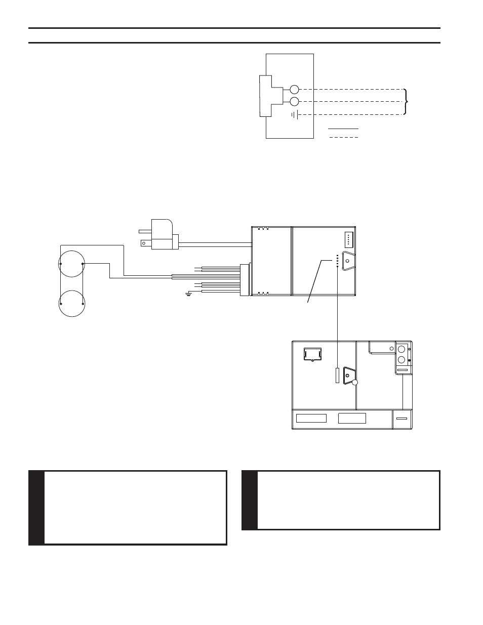
Dual
Blowers
(300 W
Max)
To Junction Box
In Fireplace
WHITE
BLACK
WHITE
BLACK
BLACK
WHITE
GREEN
Connector
Pin To Contro l Box
{
{
Optional
Light
Optional
AUX
FP2103
AC fan wiring
Dual
Blowers
(300 W
Max)
oPtIoNAl FAN/BloWeR SySteM
(BlotBlDVSC)
Installation Instructions
Wiring
1. Before installing the blower, wire the receptacle into an electri-
cal circuit. This should be done before framing the fireplace.
Wire with minimum 60° C wire in accordance with prevailing
codes.
. Remove the external junction box cover by removing the screw
from the left side of the outside firebox wall. Junction box was
installed at the factory.
3. The junction box cover has a factory installed “romex” style
strain relief connector. After connecting the wires, route the wire leads through this con-
nector. Refer to the wiring diagram in Figure 52.
oPtIoNAl FAN BloWeR SySteM
Figure 52 -
Junction Box Wiring Diagram
FP1912
Junction box wiring
8/08
Junction Box
Factory Supplied
Not Supplied
10V AC
60Hz
Figure 53 -
Blower Wiring Diagram
FP103
Control Box
optional
AC Box
W
ARNING
electrical Grounding Instructions: this
appliance is equipped with a three-prong
(grounding) plug for your protection against
shock hazard and should be plugged
directly into a properly grounded three-
prong receptacle.
W
ARNING
electrical connections should only be
performed by a qualified licensed electrician.
Main power supply must be turned off before
connecting the fan to the main electrical
power supply or performing service.