Chapter 3, Wiring, Chapter 3 wiring – MITSUBISHI ELECTRIC 2408f User Manual
Page 6
2408
f
& 2404
f
PROFIBUS Communications Handbook Wiring
2408
f
and 2404
f
PROFIBUS Communications Handbook 3-1
CHAPTER 3 WIRING
RS485 is the transmission technology used in 2404
f
and 2408
f
PROFIBUS-DP controllers.
Connections are made to the rear terminal block as follows:
Controller Terminal
Designation
Function
HB
Shield
RF Ground for cable shielding
HC
VP
5 Volts for termination network only
HD
B/B
RXD/TXD positive
HE
A/A
RXD/TXD negative
HF
D Gnd
0 Volts for termination network only
Earthing the shield
The PROFIBUS standard suggests that both ends of the transmission line be connected to safety earth. If such a course is
followed, care must be taken to ensure that differences in local earth potential do not allow circulating currents to flow, as
these can not only induce large common mode signals in the data lines, but can also produce potentially dangerous heating in
the cable. Where doubt exists, it is recommended that the shield be earthed at only one section of the network.
Do not connect the shield to DGND.
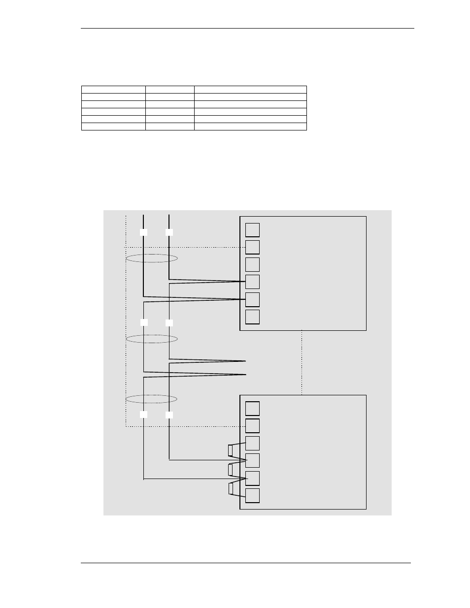
SHIELD
Station 1
HA
HB
HC
HD
HE
HF
Shield
VP (+5Vdc Voltage Potential)
B (Rx/Tx +ve)
A (Rx/Tx -ve)
DGND (Digital ground)
Not connected
B
390
Ω
Last Station
HA
HB
HC
HD
HE
HF
Shield
VP (+5Vdc Voltage Potential)
B (Rx/Tx +ve)
A (Rx/Tx -ve)
DGND (Digital ground)
Not connected
Intermediate stations
Last station only requires
terminating resistors
390
Ω
220
Ω
A
B
A
B
A
2408
f
or 2404
f
controller
2408
f
or 2404
f
controller
Twisted
pair
Twisted
pair
Figure 3-1: Connection Diagram for up to 32 Slaves.
C
ABLE
S
PECIFICATIONS