Programmer configuration, Digital input 1 configuration tab, Digital input 2 configuration tab – MITSUBISHI ELECTRIC 2408f User Manual
Page 28
2408
f
& 2404
f
PROFIBUS Communications Handbook Tag Addresses
2408
f
and 2404
f
PROFIBUS Communications Handbook 8-9
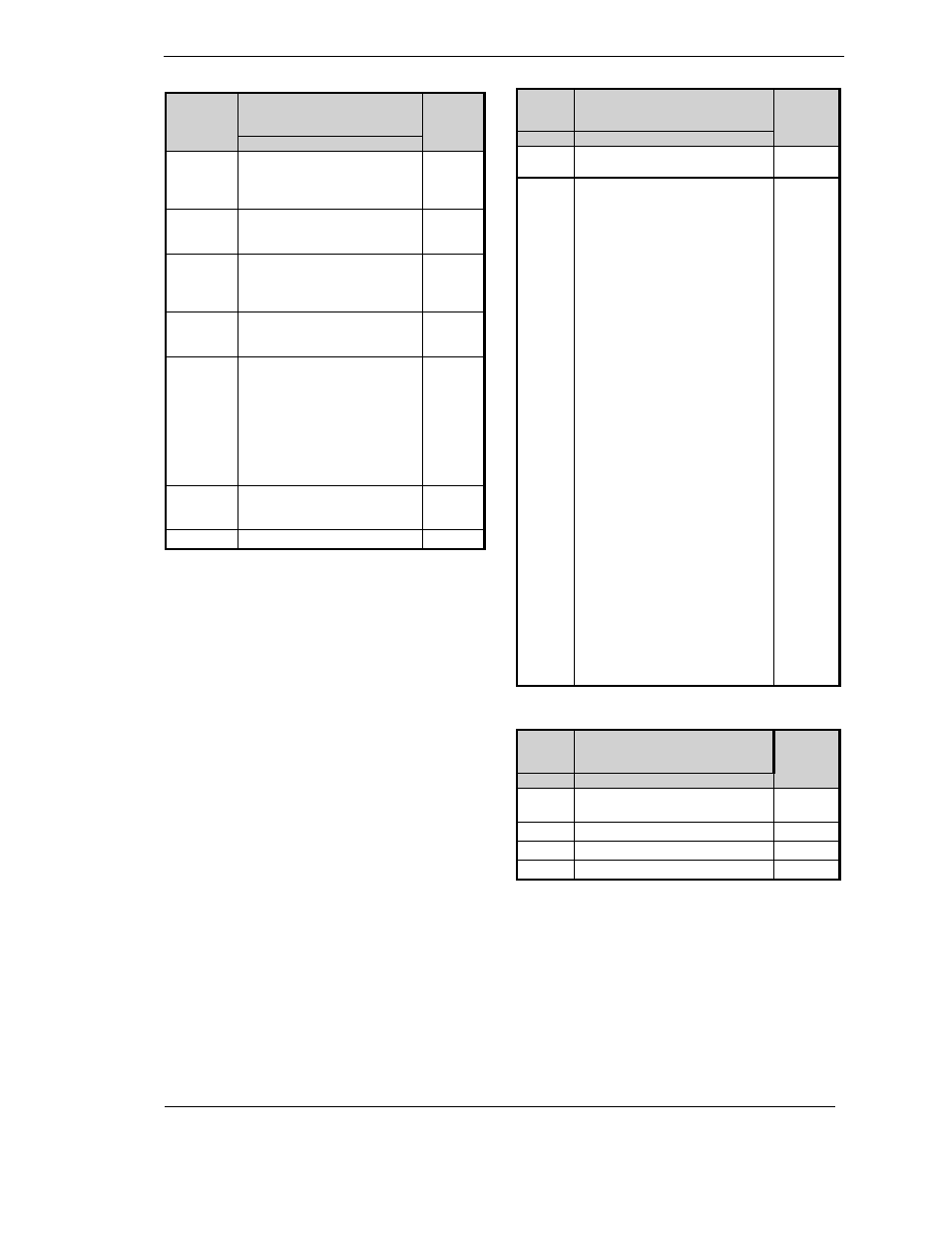
Controller
Display
Programmer
Configuration
Tag
Address
Parameter Description
06@0
06@0
Programmer type
0: None
1: Single program
4: Four programs
517
#
#
Holdback
0: Applies to whole program
1: Applies to each segment
559
0=5D
0=5D
Power fail recovery
0: Ramp back
1: Reset
2: Continue
518
5:/
5:/
Servo
0: Servo to PV
1: Servo to SP
520
/96
/96
Programmable event outputs
Version 1 controllers:
0: None
3: Three
6: Six
8: Eight
Versions 2 and 3 controllers:
0: None
1: Eight
558
@-
@-
Synchronisation of programs
0: No
1: Yes
557
Maximum Number Of Segments
211
LA
Display
Digital Input 1
Configuration Tab
Tag
Address
Parameter Description
O
O
Identity
4: Logic
12352
9.
9.
Input functions
192: None
193: Manual mode select
194: Remote setpoint select
195: Setpoint 2 select
196: PID set 2 select
197: Integral hold
198: One-shot self tune enable
199: Adaptive tune enable
200: Acknowledge alarms
201: Select full access level
202: Keylock
203: Up button
204: Down button
205: Scroll button
206: Page button
207: Run
208: Hold
209: Run/Hold
210: Reset
211: Skip
212: Holdback enabled
213: Least significant BCD digit
214: 2
nd
digit
215: 3
rd
digit
216: 4
th
digit
217: 5
th
digit
218: Most significant digit
219: Setpoint rate limit enable
220: Prog. waits at end of
segment
223: Run/Hold
224: Reset/Run
225: Standby
226: PV select
227: Advance to end of segment
240: Amps
12355
LB
Display
Digital Input 2
Configuration Tab
Tag
Address
Parameter Description
O
O
Identity:
4: Logic
12416
9.
9.
Input functions, as
above
12419
;)D)
;)D)
Low scalar
12431
;)D#
;)D#
High scalar
12430