Chapter 8, Tag addresses, Chapter 8 tag addresses – MITSUBISHI ELECTRIC 2408f User Manual
Page 20: Home tab, Status tab
2408
f
& 2404
f
PROFIBUS Communications Handbook Tag Addresses
2408
f
and 2404
f
PROFIBUS Communications Handbook 8-1
CHAPTER 8 TAG ADDRESSES
Tag addresses are used to identify parameters in the controller and are identical to the Modbus addresses which are also listed
in the Series 2000 Communications Manual, Eurotherm Part No. HA 026230. Tag addresses are used with the demand data
protcol to set up input/output data in the PLC or supervisory PC.. They are repeated here in the order in which they appear in
the GSD file.
They can also be read from the Windows Configurator by pointing to the parameter and clicking the right mouse button.
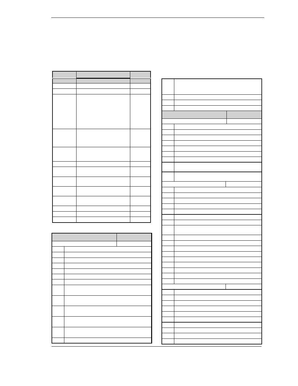
Controller
Home Tab
Tag
Display
Parameter Description
Address
Process Variable
1
0
0
Target setpoint
2
0
0
% Output power
For ON/OFF controllers the
following power levels must
be written:
Cool -100%
OFF 0%
Heat 100%
3
=D0
=D0
Working set point. Read only:
use Target set point or
currently selected set point (1
to 16) to change the value
5
,B
,B
Auto-man select
0: Auto
1: Manual
273
Pot Position
317
BB
Valve Posn (computed by
VP algorithm)
53
BB
VP Manual Output (alterable
in Man only)
60
,0
,0
Heater current (With PDSIO
mode 2)
80
DO
DO
Customer defined
identification number
629
Setpoint Span
552
Error (PV-SP)
39
Remote Input Value
26
Status Tab
Tag Address
Summary Output Status Word
75
BIT
DESCRIPTION
0
Alarm 1 State ( 0 = Safe 1 = Alarm )
1
Alarm 2 State ( 0 = Safe 1 = Alarm )
2
Alarm 3 State ( 0 = Safe 1 = Alarm )
3
Alarm 4 State ( 0 = Safe 1 = Alarm )
4
Manual Mode ( 0 = Auto 1 = Manual )
5
Sensor Break ( 0 = Good PV 1 = Sensor Broken )
6
Loop Break ( 0 = Good closed loop
1 = Open Loop )
7
Heater Fail ( 0 = No Fault
1 = Load fault detected )
8
Tune Active ( 0 = Auto Tune disabled
1 = Auto Tune active)
9
Ramp/Program Complete ( 0 = Running/Reset
1 = Complete )
10
PV out of range ( 0 = PV within table range
1 = PV out of table range )
11
DC control module fault (0= Good. 1= BAD)
12
Programmer Segment Synchronise
(0 = Waiting,
1 = Running)
13
Remote input sensor break ( 0 = Good, 1 = Bad)
14
IP1 Fault
15
Reserved
Status Tab
Tag Address
Fast Status Byte
74
BIT
DESCRIPTION
Bit 0
Alarm 1 State ( 0 = Safe 1 = Alarm )
Bit 1
Alarm 2 State ( 0 = Safe 1 = Alarm )
Bit 2
Alarm 3 State ( 0 = Safe 1 = Alarm )
Bit 3
Alarm 4 State ( 0 = Safe 1 = Alarm )
Bit 4
Manual Mode ( 0 = Auto 1 = Manual )
Bit 5
Sensor Break ( 0 = Good PV 1 = Sensor Broken )
Bit 6
Loop Break ( 0 = Good closed loop 1 = Open
Loop )
Bit 7
Heater Fail ( 0 = No Fault 1 = Load fault
detected )
Control Status Word
76
BIT
DESCRIPTION
0
Control algorithm Freeze
1
PV input sensor broken
2
PV out of sensor range
3
Self Tune failed
4
PID servo signal
5
PID debump signal
6
Fault detected in closed loop behaviour (loop
break)
7
Freezes the integral accumulator
8
Indicates that a tune has completed successfully
9
Direct/reverse acting control
10
Algorithm Initialisation flag
11
PID demand has been limited.
12
Autotune enabled
13
Adaptive tune enabled
14
Automatic Droop compensation enabled
15
Manual / Auto mode switch
Instrument Status Word
77
BIT
DESCRIPTION
0
Config/Oper mode switch
1
Disables limit checking
2
SRL ramp running (Read Only)
3
Remote setpoint active
4
Alarm acknowledge switch.
5
Reserved
6
Reserved
7
Reserved
8
Reserved