Chapter 2, Principles of operation, Chapter 2 principles of operation – MITSUBISHI ELECTRIC 2408f User Manual
Page 4
2408f & 2404
f
PROFIBUS Communications Handbook Principles of Operation
2408
f
and 2404
f
PROFIBUS Communications Handbook 2-1
CHAPTER 2 PRINCIPLES OF OPERATION
PROFIBUS-DP distinguishes between master devices and slave devices. It allows slave devices to be connected on a single
bus thus eliminating considerable plant wiring typical with conventional communications systems. Figure 2-1 compares the
two systems.
Master devices determine the data communication on the bus. A master can send messages without an external request when
it holds the bus access rights (the token). Masters are also called active stations in the PROFIBUS protocol.
Slave devices are peripheral devices. Typical slave devices include input/output devices, valves, motor drives and measuring
transmitters. The 2408
f
and 2404
f
series Temperature Controllers are intelligent slaves. This means they will only respond to
a master when requested to do so.
PROFIBUS-DP is based around the idea of a ‘cyclical scan’ of devices on the network, during which ‘input’ and ‘output’
data for each device is exchanged.
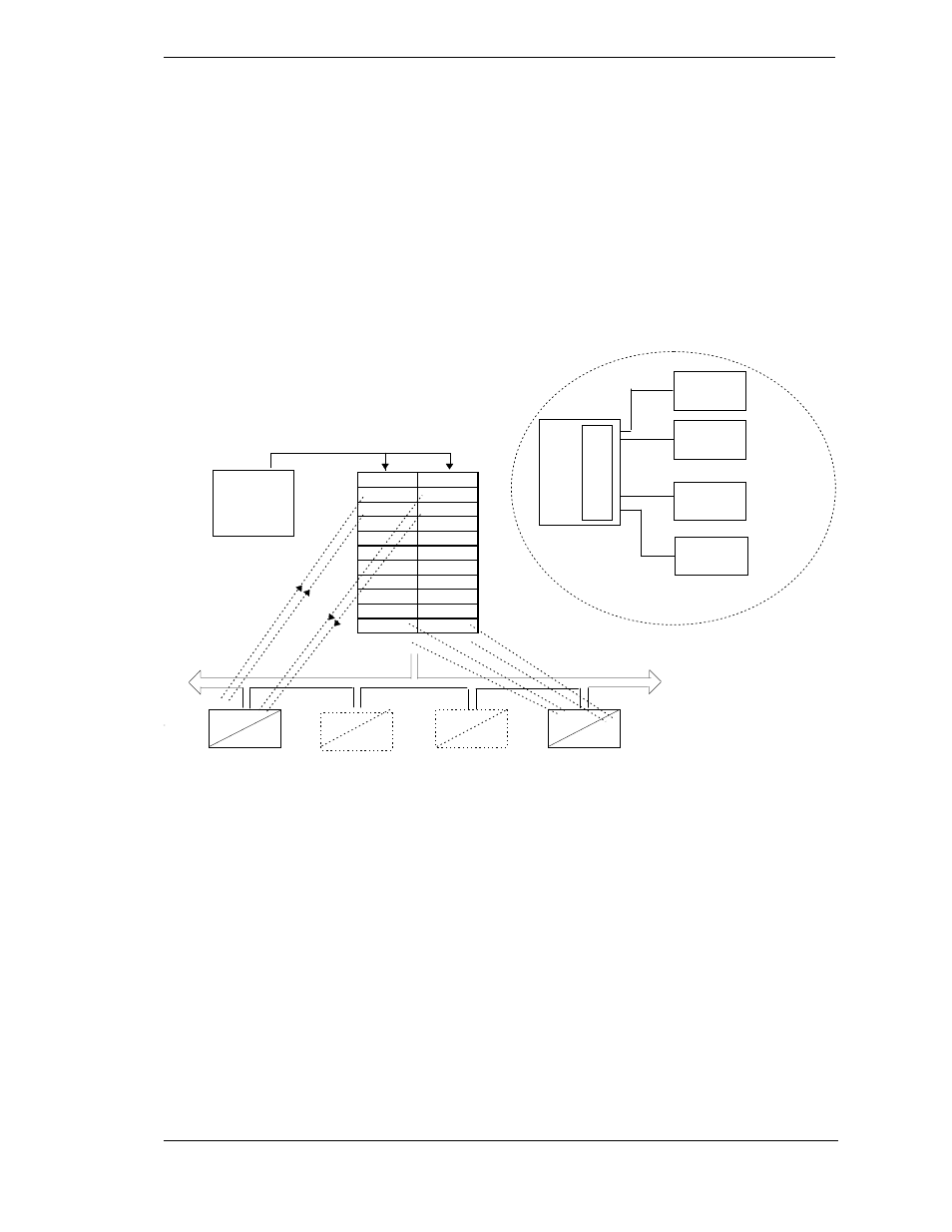
Figure 2-1: PROFIBUS compared with conventional comms. systems.
I/O Data Exchange
The process of reading the inputs and writing to the outputs is known as an I/O data exchange. Typically, the parameters from
each slave device will be mapped to an area of PLC input and output registers, or a single function block, so that the
controlling ladder logic or program interfaces with the device as if it were an internally fitted module. It is NOT necessary,
therefore, for the programmer to know anything about the physical network. The process of network configuration is usually
performed using a PC based program which allows the devices on the network to be defined and device parameters to be
mapped into the PLC registers or function blocks.
The cyclical scan occurs in the following order:
1. Values from each slave device, ‘Input Data’, are first scanned over the network into a pre-defined set of input registers in
the master controller. Such values might be a set of digital input readings for a digital input unit, or the measured
temperature and alarm status from a PID controller.
2. The master then runs its control program, (such as a ladder logic program) using the input data read from the slave
devices.
3. The master writes output values (output data) into a pre-defined set of output registers. For example, one of the digital
inputs read in the input data might be used to select one of a set of setpoints to be sent to the PID controller.
4. These outputs are then written to each slave device, and the scan-process-write cycle repeats.
Input
Output
Physical I/O
Ladder
Program
PLC I/O Mapping
Slave 1
Slave 2
Slave 3
Slave 4
PLC
Physical
Actuator 1
Figure 2-1a: Plant wiring
conventional comms. systems
I/O scanning
Physical
Actuator 2
Physical
Actuator 3
Physical
Actuator 4
I/O
Mod-
ules
Input
Input
Output
Output