MITSUBISHI ELECTRIC 2408f User Manual
Page 11
Controller Set Up & Network Configuration 2408
f
& 2408
f
PROFIBUS Communications Handbook
4-4 2408
f
and 2404
f
PROFIBUS Communications Handbook
P
ROFIBUS
D
IAGNOSTICS
One of the features of PROFIBUS-DP is that high priority diagnostic information is provided for each slave. The 2400
f
Series uses the ‘Ext_Diag_Data’ area of this message (bytes 7 and 8) to send a word containing 16 bits of information
pertaining to the process and alarm status of the controller: The documentation supplied with your master should provide
further details on how to access diagnostic information.
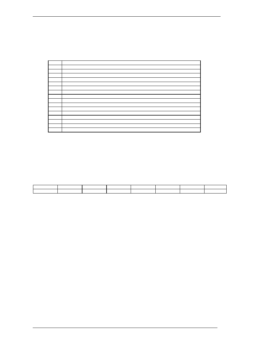
BIT
DESCRIPTION
0
Alarm 1 State ( 0 = Safe 1 = Alarm )
1
Alarm 2 State ( 0 = Safe 1 = Alarm )
2
Alarm 3 State ( 0 = Safe 1 = Alarm )
3
Alarm 4 State ( 0 = Safe 1 = Alarm )
4
Manual Mode ( 0 = Auto 1 = Manual )
5
Sensor Break ( 0 = Good PV 1 = Sensor Broken )
6
Loop Break ( 0 = Good closed loop 1 = Open Loop )
7
Heater Fail ( 0 = No Fault 1 = Load fault detected )
8
Tune Active ( 0 = Auto Tune disabled 1 = Auto Tune active)
9
Ramp/Program Complete ( 0 = Running/Reset 1 = Complete )
10
PV out of range ( 0 = PV within table range 1 = PV out of table range )
11
DC control module fault (0= Good. 1= BAD)
12
Programmer Segment Synchronise (0 = Waiting, 1 = Running)
13
Remote input sensor break (0 = Good, 1 = Bad)
14
IP1 Fault
15
Reserved
Table 4-2: Summary Output Status Word
A ‘new diagnostics’ event will occur whenever any of the monitored events changes state...
Diagnostics Example
The example below may be returned which gives a summary of the Output Status Word information shown in the table
above.
Byte 1
Byte 2
Byte 3
Byte 4
Byte 5
Byte 6
Byte 7
Byte 8
XX
XX
24
XX
XX
03
40
30
Byte 6 signifies 3 bytes of information are included
Bytes 7 & 8 are 4030Hex or 01 00 00 00 00 11 00 00 Binary
From table 4-1:
Bit 4 is set Meaning the controller is in Manual Mode
Bit 5 is set Meaning the controller is in Sensor Break
Bit 14 is set Meaning the controller is in IP1 Fault
Global Commands
This is a further PROFIBUS-DP feature, which is not supported by the 2400f series of temperature controllers.