Motorola Canopy Powerline MU User Manual
Page 99
Powerline MU User Guide
March, 2007
Issue 2.0
Page 99 of 112
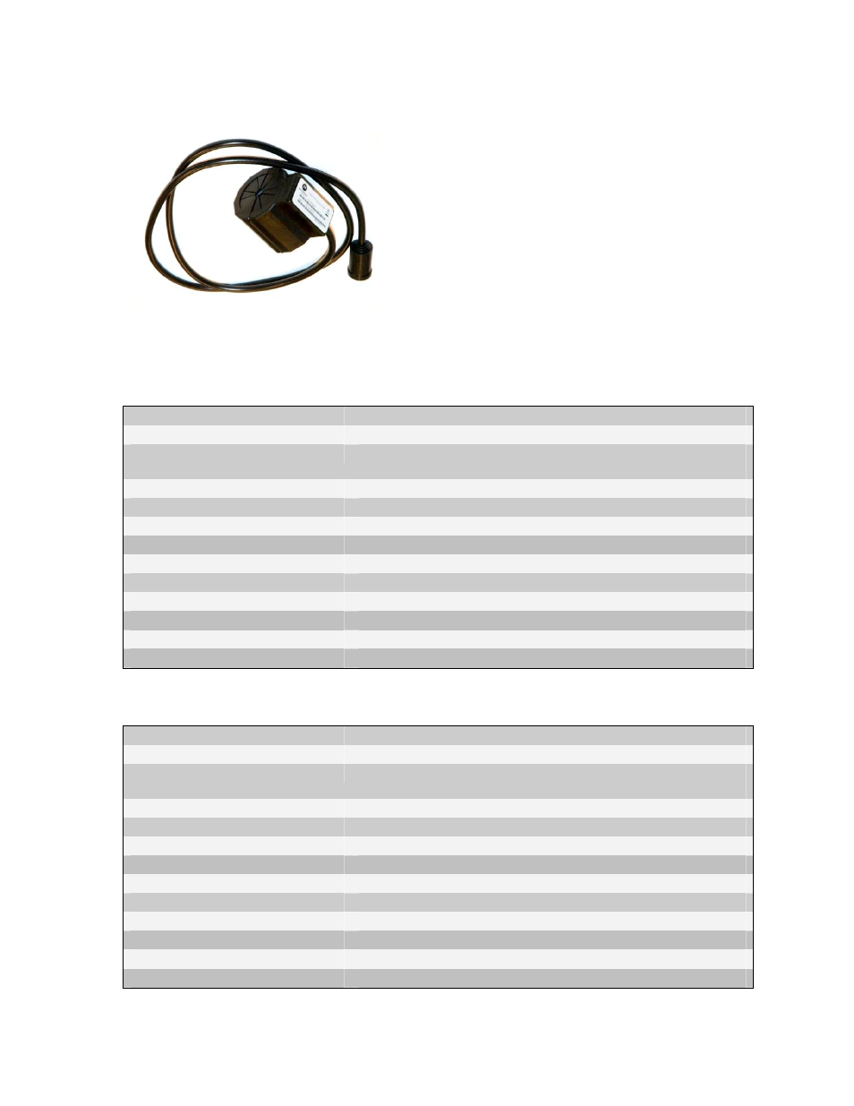
Powerline MU Inductive Coupler
•
Useful in individually-metered and multiple
transformer buildings such as apartments and
condominiums which have one or more meter
banks with meters that monitor power
consumption to individual residences
•
Connect one coupler per phase just before the
meter bank in the Termination Cabinet over the
insulated portion of the electric cable
•
Provides efficiency in signal distribution by
injecting on the larger wires just before the meter bank and subsequent branching to
individual residences with no contact to the actual metal conductor
•
Three coupler sizes to accommodate various wiring gauges
500
Part Number
0171486N21
Part Name
Powerline MU Inductive Coupler 500
Description
Optional Powerline MU coupler to Induce Signal onto in-
building cables before the Meter Bank.
High Voltage Interface
Fits up to 500 MCM cable rated 380A
Cable
75 Ohm Coaxial
Connectors
F-Connector (Coaxial)
Center Conductor
600v rated 22-gauge stranded copper THHN wire
Dimensions
2.8 in x 2.3 in x 2.2 in (70.14 mm x 58.3 mm x 55mm)
Inner Diameter of core
1 in (25.4 mm)
Outer Diameter of Core
2.02 in (51.31 mm)
Weight
.90 lbs
Operating temperature
-40°C to 55°C (-40°F to 131°F)
Safety
UL authorization (In conjunction with Powerline MU Gateway)
250
Part Number
0171486N23
Part Name
Powerline MU Inductive Coupler 250
Description
Optional Powerline MU coupler to Induce Signal onto in-
building cables before the Meter Bank.
High Voltage Interface
Fits up to 250 MCM cable rated 255A
Cable
75 Ohm Coaxial
Connectors
F-Connector (Coaxial)
Center Conductor
600v rated 22-guage stranded copper THHN wire
Dimensions
2.8 in x 2.3 in x 2.2 in (70.14 mm x 58.3 mm x 55mm)
Inner Diameter of core
.76 in (19.4 mm)
Outer Diameter of Core
2.02 in (51.31 mm)
Weight
.99 lbs
Operating temperature
-40°C to 55°C (-40°F to 131°F)
Safety
UL authorization (In conjunction with Powerline MU Gateway)