Matrox Electronic Systems II User Manual
Page 34
34 Chapter 2: Hardware installation
Connecting a video input to Meteor-II /Standard for PCI
or CompactPCI
You can connect video sources to Matrox Meteor-II /Standard’s
video input connector, using the optional DBHD44-TO-13BNC
cable. This cable has thirteen BNC connectors and a 44-pin
high-density D-Subminiature plug. The wires of the cable are
color-coded as follows. Connect your cameras accordingly.
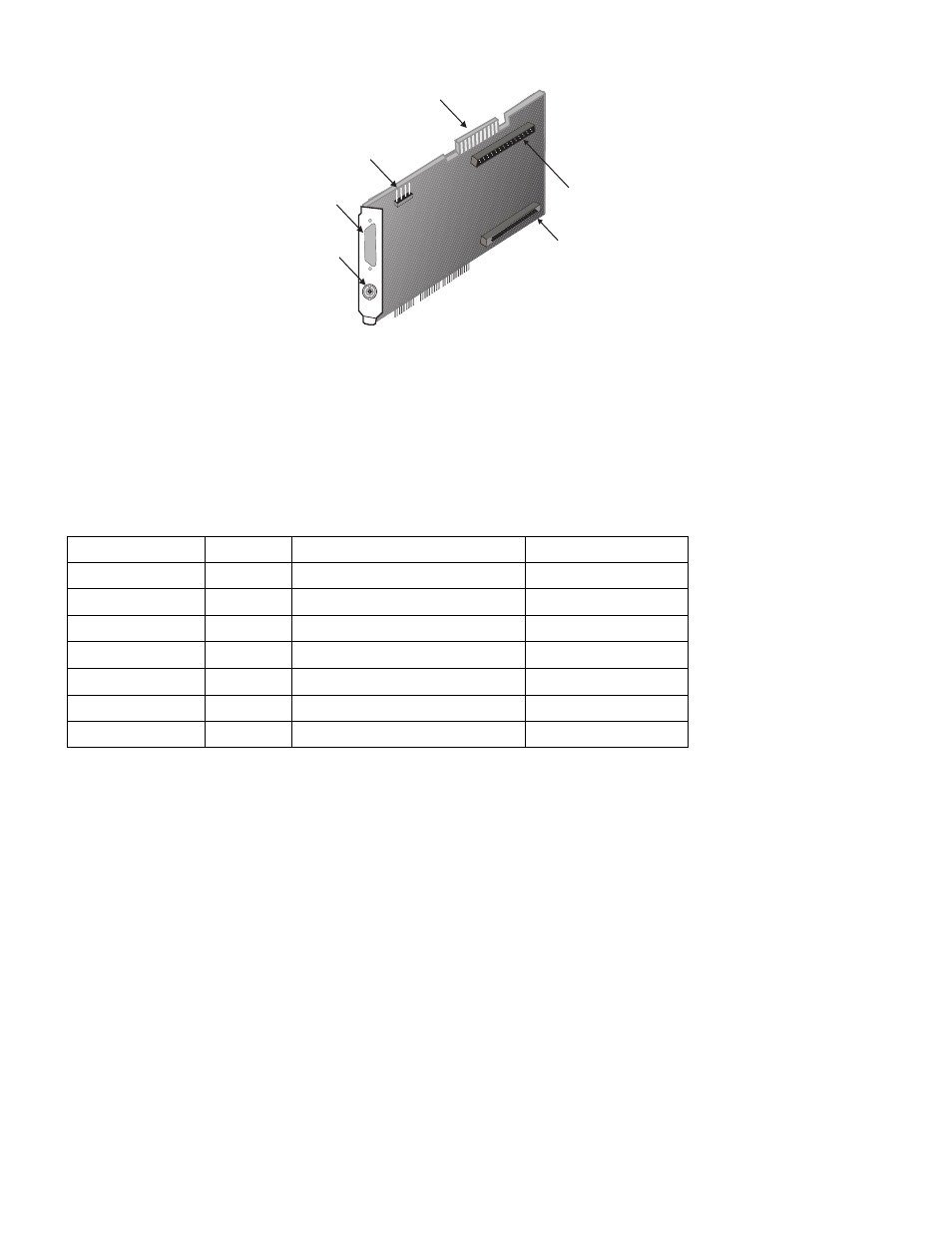
VMChannel
Connector 1 (male) for
expansion module
Connector 2 (female) for
expansion module
Video input
Auxiliary power supply
input
BNC
Wires
Signals
Expected Input
Form factor
RED (1)
VID_IN1
Analog Video Input1 or Y1
PCI, CompactPCI
GREEN (2)
VID_IN2
Analog Video Input2 or C1
PCI, CompactPCI
BLUE (3)
VID_IN3
Analog Video Input3 or Y2
PCI, CompactPCI
BLACK (4)
VID_IN4
Analog Video Input4 or C2
PCI, CompactPCI
WHITE (5)
VID_IN5
Analog Video Input5 or C4
PCI, CompactPCI
YELLOW (6)
VID_IN6
Analog Video Input6 or Y3
PCI, CompactPCI
PURPLE (7)
VID_IN7
Analog Video Input7 or C3
PCI, CompactPCI