Tv back panel, 9front-panel indicators, Ant 1/ant 2 (antenna) – MITSUBISHI ELECTRIC WD-65735 User Manual
Page 5: Avr audio output, Digital audio output, Composite video (input 1, input 3), Component video (input 1, input 2)
8
1. Television Overview
1. Television Overview
9
Front-Panel Indicators
LAMP Indicator
LED Color TV Condition
Additional Information
None
Normal TV on or standby condition.
Normal operation.
Green
TV just powered off and lamp is
cooling.
Starts to blink 60 seconds after turning off TV. TV can be turned
back on before blinking starts or after blinking stops, but not
while the indicator is blinking. Normal operation.
Yellow
1. Lamp access door is open or
not secure.
TV will not operate until lamp access door is secure. See
Appendix E for installation information.
2. No lamp installed.
TV will not operate without a lamp. See Appendix E for installa-
tion information.
Red
Lamp no longer illuminates and has
reached the end of the lamp life.
Replace the lamp. The TV will not operate when the lamp no
longer illuminates. See Appendix E for installation information.
Off
Steady On
Slow Blinking
Fast Blinking
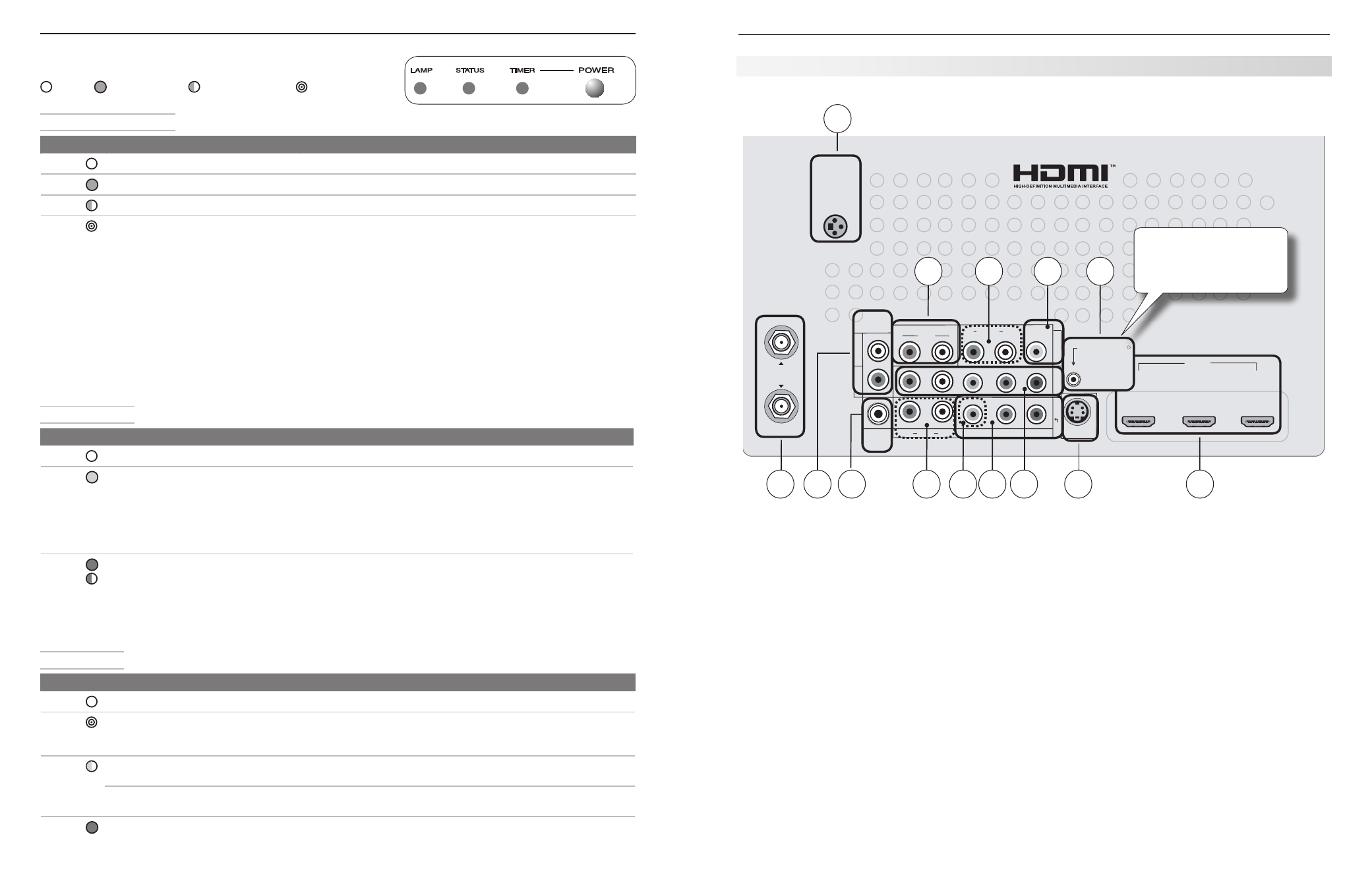
TV Back Panel
1. ANT 1/ANT 2 (Antenna)
If you are connecting an antenna or direct cable service
without a cable box, connect the main antenna or cable
source to
ANT 1. Use ANT 2 for a second source.
ANT 1 and ANT 2 can each receive digital and analog
over-the-air channels from a VHF/UHF antenna or non-
scrambled digital/analog cable source.
2. AVR AUDIO OUTPUT
Use
AVR AUDIO OUTPUT to send analog audio of the
program currently shown on the screen to an analog
A/V surround sound receiver or stereo system. Digital
audio from digital channels and HDMI devices is con-
verted to analog audio by the TV. This is the only audio
connection needed between it and the TV if using an
analog A/V receiver or stereo system.
3. DIGITAL AUDIO OUTPUT
This output sends Dolby Digital or PCM digital audio to
your digital A/V surround sound receiver. Analog audio
from analog channels and devices and HDMI devices is
converted by the TV to PCM digital audio. If you have
a digital A/V receiver, in most cases this is the only
audio connection needed between the TV and your A/V
receiver.
4. Composite Video (INPUT 1, INPUT 3)
Use the
VIDEO jacks to connect a VCR, DVD player,
standard satellite receiver, or other A/V device to the
TV. Use the adjacent
AUDIO R and L inputs for INPUT
1 or INPUT 3 if you wish to send audio to the TV. Note
that the
INPUT 3 composite video jack is automatically
disabled when you connect to
S-VIDEO (item 6).
5. Component Video (INPUT 1, INPUT 2)
Y Pb Pr Component Video (480i/480p/720p/1080i)
Use these jacks to connect devices with component
video outputs, such as DVD players, external HDTV
receivers, or compatible video game systems. Use the
adjacent
AUDIO R and L jacks for INPUT 1 or INPUT 2
if you wish to send audio to the TV. See Appendix A
specifications for signal compatibility.
STATUS Indicator
LED Color TV Condition
Additional Information
None
Normal TV on or standby condition. Normal operation.
Yellow
TV is too hot.
The TV will display a warning message and shut off if it overheats.
• Ambient room temperature may be too high. Turn off the TV
and let the room temperature to drop.
• Clear blocked air vents. Ensure at least a four-inch clear-
ance on all sides of the TV.
• Clean the lamp-cartridge air filter. See Appendix E.
Red
TV may require service.
Turn off the TV and unplug the set from the AC power source.
Wait one minute and then plug the set back in. See Appendix D.
If the LED is still on, contact your dealer or a Mitsubishi Autho-
rized Service Center. Go to www.mitsubishi-tv.com or call
1-800-332-2119 to receive Authorized Service Center information.
POWER/TIMER Indicator
LED Color TV Condition
Additional Information
None
TV is powered off.
Normal operation.
Green
TV is powered on.
Normal operation.
Green
TV powered off, auto-on timer is set. Normal operation. TV can be turned on at any time.
Green
TV just plugged into AC outlet.
•
Wait approximately two minutes for blinking to stop before
turning on. Normal operation.
AC just restored after power failure.
•
TV is rebooting after System
•
Reset used.
TV is rebooting after power
•
fluctuation or receiving abnor-
mal digital signals from a digital
channel or digital device.
You have begun the procedure
•
to update software from an
authorized flash memory device.
HDMI
3D
GLASSES
EMITTER
AVR
AUDIO
OUTPUT
DIGITAL
AUDIO
OUTPUT
L
R
AUDIO
L
R
(480i / 480p / 720p / 1080i)
L
R
DVI/PC
INPUT
VIDEO
AUDIO
R
L
Y
Pb
Pr
AUDIO
Pb
Y/ VIDEO
Pr
VIDEO: 480i/480p/720p/1080i/1080p
AUDIO: PCM STEREO
PC: VGA, W-VGA, SVGA, W-SVGA,
XGA, W-XGA, SXGA, 720p/ 1080p
1
2
3
HDMI
IR-
NetCommand
Output / External
Controller Input
R
INPUT
3
INPUT
2
INP
UT
1
S-VIDEO
INPUT 3
ANT 2 / AUX
ANT 1 / MAIN
1
6
5
7
2
3
4
9
5
8
9
11
10
4
IR NetCommand Output/
External Controller Input
available on 736 and 835
series models.