Wall outlet cable (no cable box), Antennas with separate uhf and vhf leads, Antenna with a single lead – MITSUBISHI ELECTRIC WD-65735 User Manual
Page 11: Vcr to an antenna or wall outlet cable, Tv connections 3. tv connections, An antenna (or cable) to ant 2, Figure 4. wall outlet cable, Uhf/vhf combiner. push the combiner onto, Ant 1 on the tv back panel, 7$3 57cbdlqbofm
20
3. TV Connections
3. TV Connections
21
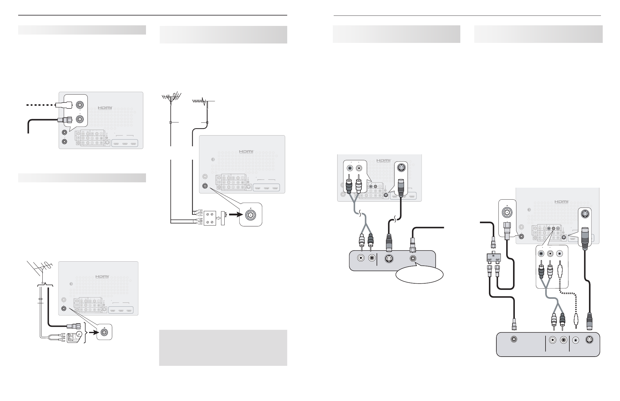
Wall Outlet Cable (no cable box)
It is very important to connect the incoming cable for
your primary viewing source to
ANT 1.
Connect the primary incoming coaxial lead cable to
1.
ANT 1 on the TV back panel.
For an optional secondary antenna source, connect
2.
an antenna (or cable) to
ANT 2.
HDMI
3D
GLASSES
EMITTER
AVR
AUDIO
OUTPUT
DIGITAL
AUDIO
OUTPUT
L
R
L
R
(480i / 480p / 720p / 1080i)
L
R
DVI/PC
INPUT
VIDEO
Y
Pb
Pr
AUDIO
Pb
Y/ VIDEO
Pr
VIDEO: 480i/480p/720p/1080i/1080p
AUDIO: PCM STEREO
PC: VGA, W-VGA, SVGA, W-SVGA,
XGA, W-ZGA, SXGA, 720p/ 1080p
1
2
3
HDMI
IR-
NetCommand
Output / External
Controller Input
R
INPUT
3
INPUT
2
INP
UT
1
S-VIDEO
INPUT 3
AUDIO
R
L
AUDIO
ANT 2 / AUX
ANT 1 / MAIN
ANT 2 / AUX
ANT 1 / MAIN
ANT 2 / AUX
ANT 1 / MAIN
"6%*0
47*%&0
065
-
3
"OZ47JEFPEFWJDF
57CBDLQBOFM
$"#-&*/PS
4"5&--*5&*/
*ODPNJOH
DBCMFGSPN
XBMM
5P"/5
5P"/5
Figure 4. Wall Outlet Cable
A.
For an antenna with flat twin leads
Required: 300-ohm-to-75-ohm transformer.
A1. For an antenna with flat twin leads, connect the
300-ohm twin leads to the 300-ohm-to-75-ohm
transformer.
A2. Push the 75-ohm side of the transformer onto
ANT 1 on the TV back panel.
B.
For cable or antenna with coaxial lead
Connect the coaxial lead directly to
ANT 1 on the
TV back panel.
Antennas with Separate UHF and
VHF Leads
Required: UHF/VHF combiner
Connect the UHF and VHF antenna leads to the
1.
UHF/VHF combiner.
Push the combiner onto
2.
ANT 1 on the TV back
panel.
HDMI
3D
GLASSES
EMITTER
AVR
AUDIO
OUTPUT
DIGITAL
AUDIO
OUTPUT
L
R
L
R
(480i / 480p / 720p / 1080i)
L
R
DVI/PC
INPUT
VIDEO
Y
Pb
Pr
AUDIO
Pb
Y/ VIDEO
Pr
VIDEO: 480i/480p/720p/1080i/1080p
AUDIO: PCM STEREO
PC: VGA, W-VGA, SVGA, W-SVGA,
XGA, W-XGA, SXGA, 720p/ 1080p
1
2
3
HDMI
IR-
NetCommand
Output / External
Controller Input
R
INPUT
3
INPUT
2
INP
UT
1
S-VIDEO
INPUT 3
AUDIO
R
L
AUDIO
ANT 2 / AUX
ANT 1 / MAIN
ANT 1 / MAIN
"6%*0
47*%&0
065
-
3
6)'
7)'
6)'BOUFOOB
DIBOOFMTo
&YUFSOBMBOUFOOB
PSDBCMF
'MBUUXJOMFBE
7)'BOUFOOB
DIBOOFMTo
PINUP
PINDPNCJOFS
"OZ47JEFPEFWJDF
#BDL
WJFX
4JEF
WJFX
57CBDLQBOFM
"
#
"
"
$"#-&*/PS
4"5&--*5&*/
*ODPNJOH
DBCMFGSPN
XBMM
5P"/5
5P"/5
Figure 6. Connecting separate UHF and VHF Antennas
Mitsubishi strongly recommends you avoid using
antennas with flat twin leads. Flat twin lead
antenna wires are subject to interference which
may adversely affect the performance of the TV.
We recommend using coaxial antenna cable.
Antenna with a Single Lead
HDMI
3D
GLASSES
EMITTER
AVR
AUDIO
OUTPUT
DIGITAL
AUDIO
OUTPUT
L
R
L
R
(480i / 480p / 720p / 1080i)
L
R
DVI/PC
INPUT
VIDEO
Y
Pb
Pr
AUDIO
Pb
Y/ VIDEO
Pr
VIDEO: 480i/480p/720p/1080i/1080p
AUDIO: PCM STEREO
PC: VGA, W-VGA, SVGA, W-SVGA,
XGA, W-XGA, SXGA, 720p/ 1080p
1
2
3
HDMI
IR-
NetCommand
Output / External
Controller Input
R
INPUT
3
INPUT
2
INP
UT
1
S-VIDEO
INPUT 3
AUDIO
R
L
AUDIO
ANT 2 / AUX
ANT 1 / MAIN
ANT 1 / MAIN
ANT 1 / MAIN
"6%*0
47*%&0
065
-
3
PIN
nBUUXJO
MFBE
PIN
DPBYJBM
MFBE
0QUJPOBMPIN
UPPINNBUDIJOH
USBOTGPSNFS
"OZ47JEFPEFWJDF
57CBDLQBOFM
"
#
"
"
$"#-&*/PS
4"5&--*5&*/
*ODPNJOH
DBCMFGSPN
XBMM
5P"/5
5P"/5
Figure 5. Connecting a Single Antenna Lead
Figure 8. Connecting a VCR to an Antenna or Wall
Outlet Cable
VCR to an Antenna or
Wall Outlet Cable
Required: Two-way RF splitter, two coaxial cables, right
and left analog audio cables, either S-video or compos-
ite video cable.
Connect the incoming cable or antenna to
1.
IN on the
RF splitter.
Connect one coaxial cable from
2.
OUT on the RF
splitter to
ANTENNA IN on the VCR back panel.
Connect one coaxial cable from
3.
OUT on the RF
splitter to
ANT 1 on the TV back panel.
Connect either an S-Video or composite video
4.
cable from
VIDEO OUT on the VCR back panel to a
VIDEO composite or S-VIDEO jack on the TV back
panel.
Connect only one type of video cable;
S-Video is recommended, if available.
To use the TV speakers with the VCR, connect left
5.
(white) and right (red) audio cables from
AUDIO OUT
on the VCR to the associated
AUDIO L and R jacks
on the TV back panel. If your VCR is mono (non-
stereo), connect only the white (left) cable.
HDMI
3D
GLASSES
EMITTER
AVR
AUDIO
OUTPUT
DIGITAL
AUDIO
OUTPUT
L
R
L
R
(480i / 480p / 720p / 1080i)
L
R
DVI/PC
INPUT
VIDEO
Y
Pb
Pr
AUDIO
Pb
Y/ VIDEO
Pr
VIDEO: 480i/480p/720p/1080i/1080p
AUDIO: PCM STEREO
PC: VGA, W-VGA, SVGA, W-SVGA,
XGA, W-ZGA, SXGA, 720p/ 1080p
1
2
3
HDMI
IR-
NetCommand
Output / External
Controller Input
R
INPUT
3
INPUT
2
INP
UT
1
S-VIDEO
INPUT 3
AUDIO
R
L
AUDIO
ANT 2 / AUX
ANT 1 / MAIN
S-VIDEO
INPUT 3
AUDIO
R
L
AUDIO
R
L
S-VIDEO
INPUT 3
VIDEO
VIDEO
ANT 1 / MAIN
ANT 1 / MAIN
"6%*0065
47*%&0
065
7*%&0
065
-
3
"/5&//"
*/
7$3
57CBDLQBOFM
$"#-&*/PS
4"5&--*5&*/
*ODPNJOH
DBCMF
Standard Cable Box, Satellite Receiver,
or Other Device with S-Video
Required: S-Video cable and left/right analog stereo
audio cables.
Connect the cable from the outside cable or satel-
1.
lite service to
CABLE IN or SATELLITE IN on the
cable box or satellite receiver.
Connect an S-Video cable from
2.
S-VIDEO OUT on
the cable box or satellite receiver back panel to
INPUT 3 S-VIDEO on the TV back panel.
Connect left (white) and right (red) audio cables
3.
from
AUDIO OUT on the cable box or satellite
receiver to
INPUT 3 AUDIO L and R on the TV back
panel.
Note: Refer to the cable box or satellite receiver
Owner’s Guide for cable or dish antenna con-
nections to the receiver.
HDMI
3D
GLASSES
EMITTER
AVR
AUDIO
OUTPUT
DIGITAL
AUDIO
OUTPUT
L
R
L
R
(480i / 480p / 720p / 1080i)
L
R
DVI/PC
INPUT
VIDEO
Y
Pb
Pr
AUDIO
Pb
Y/ VIDEO
Pr
VIDEO: 480i/480p/720p/1080i/1080p
AUDIO: PCM STEREO
PC: VGA, W-VGA, SVGA, W-SVGA,
XGA, W-ZGA, SXGA, 720p/ 1080p
1
2
3
HDMI
IR-
NetCommand
Output / External
Controller Input
R
INPUT
3
INPUT
2
INP
UT
1
S-VIDEO
INPUT 3
AUDIO
R
L
AUDIO
ANT 2 / AUX
ANT 1 / MAIN
S-VIDEO
INPUT 3
AUDIO
R
L
AUDIO
R
L
S-VIDEO
INPUT 3
"6%*0
47*%&0
065
-
3
"OZ47JEFPEFWJDF
57CBDLQBOFM
$"#-&*/PS
4"5&--*5&*/
*ODPNJOH
DBCMFGSPN
XBMM
Figure 7. Connecting a device with S-Video