Brake shoes – Grizzly G0709 User Manual
Page 74
-72-
Model G0709 (Mfg. Since 5/11)
brake Shoes
if the brake responds poorly, verify that the all link-
age is tight and that the belts are tight and free of
oil or grease. replace the brake shoe set if the
lining thickness is
3
⁄
16
" or less. When inspecting
for amount of brake wear measure from the fol-
lowing locations:
• if riveted linings are used, the measurement is
taken from the rivet heads to the lining surface
as viewed from the brake pad surface.
• if bonded linings are used, the measurement
is taken from the metal shoe surface to the
surface of the lining as viewed from the side
of the brake shoe.
When inspecting the drum, if the drum pulley is
bell-mouthd, cracked, or shows deep groves,
replace it. For minor scoring, the drum pulley can
be dressed with sandpaper or turned on a lathe.
Tools Needed
Qty
hex Wrench 5mm .............................................. 1
Wrench 17mm.................................................... 1
needle-nose pliers ........................................... 1
Basic Caliper ..................................................... 1
To check/replace the brake linings:
1. disConneCt lAthe FroM poWer!
2. remove the headstock gear cover.
3. loosen the motor mount bolts (figure 116)
and remove the belts.
4. have another person step on the brake pedal
to lock the pulley in place, and remove the
pulley cap screw shown in
figure 116.
5. step off the brake pedal and remove the pul-
ley.
figure 117 shows the pulley removed
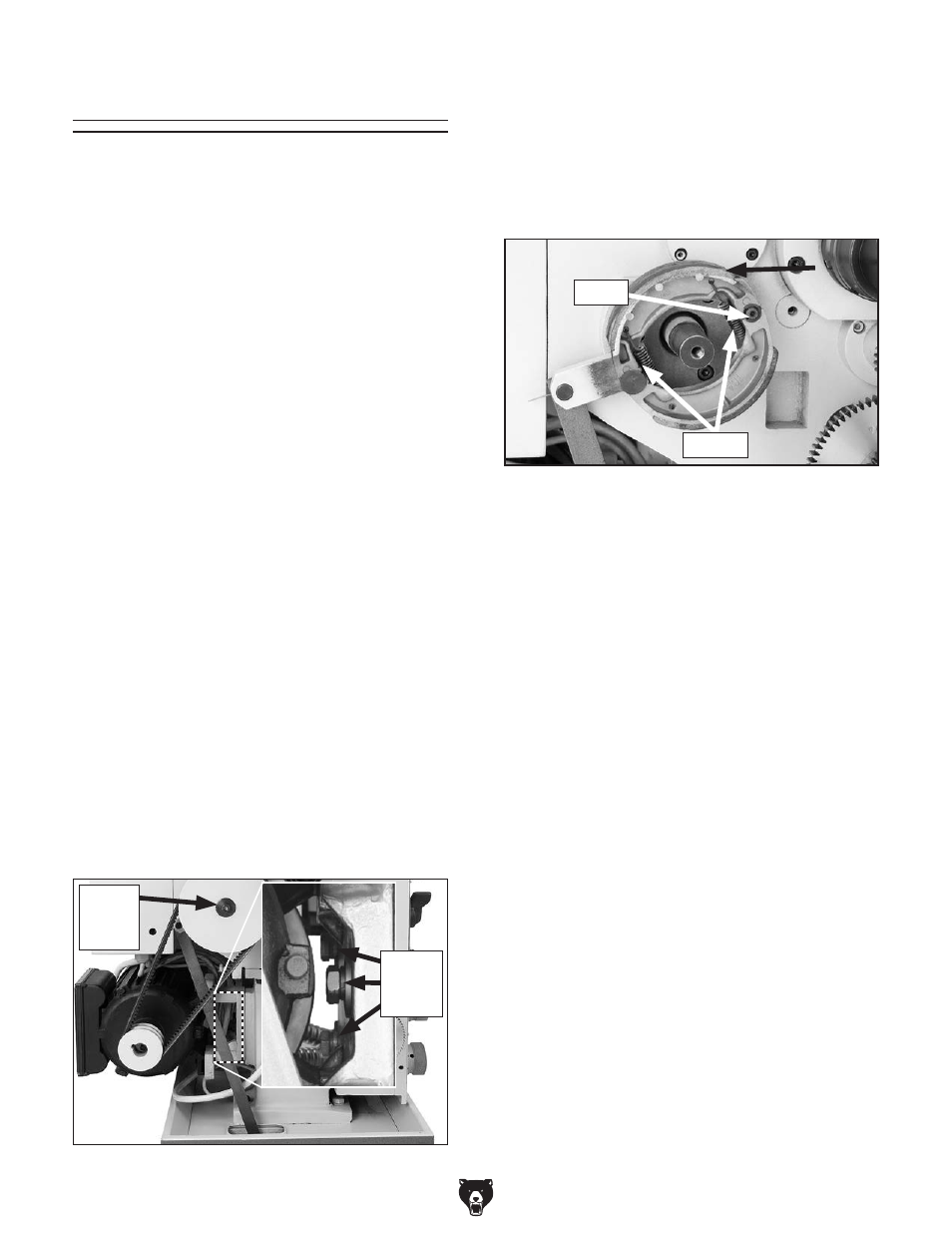
and the brake shoes exposed.
figure 116. pulley cap screw.
Motor
Mount
Bolts
pulley
Cap
screw
Brake
linings
6. using your calipers, measure the thickness of
the brake linings.
— if the linings are thicker than
3
⁄
16
" as
described earlier, then replacement is not
required. re-assemble the lathe in the
opposite manner as outlined in
Steps
2–5.
—if linings are oil-soaked from over lubrica-
tion of the adjacent gearing, clean and
properly lubricate the gears as outlined in
Maintenance on page 53. then proceed
to
Step 7.
—if the brakes linings are
3
⁄
16
" or thinner, pro-
ceed to
Step 7.
7. put on safety glasses and remove the e-clip,
springs, and brake shoes shown in
figure
117.
8. replace or dress the drum pulley as
required.
9. install the brake shoes, springs, and e-clip.
10. install the pulley and re-assemble in the
opposite manner that you disassembled it in
Steps 2–5.
11. start the lathe and test the brake operation.
figure 117. Brake assembly.
e-Clip
springs