V-belt replacement, Gap insert removal & installation – Grizzly G0709 User Manual
Page 72
-70-
Model G0709 (Mfg. Since 5/11)
v-belt Replacement
Tools Needed
Qty
phillips screwdriver #2 ...................................... 1
Wrench 17mm.................................................... 1
To replace the v-belts on the lathe:
1. disConneCt lAthe FroM poWer!
2. remove the headstock gear cover.
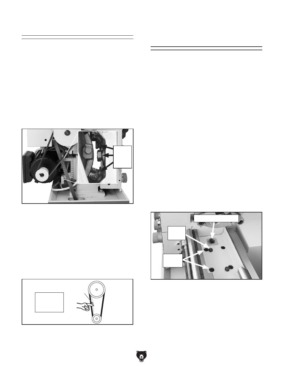
3. loosen the motor mount bolts shown in
figure 113, and slide the motor up, remove
the belts.
figure 113. location of motor mount bolts.
Motor
Mount
Bolts
Gap Insert Removal
& Installation
this lathe is equipped with a removable gap
insert that will allow for turning large diameter
workpieces. the gap was seated, pre-loaded,
and then ground for precise mating and alignment
at the factory. removing the gap can cause the
lathe insert to slightly spring out of shape. When
re-installed, there is no guarantee that original
alignment and flush mating will be the same. For
this reason, removing the gap is considered a
permanent alteration to the lathe, even if it is later
re-installed.
Tools Needed
Qty
open end Wrench 14mm .................................. 1
hex Wrench 8mm .............................................. 1
heavy dead Blow hammer ............................... 1
Miscellaneous C-Clamps ................ As required
Wooden Blocks ............................... As required
To remove the gap:
1. disConneCt lAthe FroM poWer!
2. remove the four cap screws that secure the
gap to the bed (see
figure 115).
figure 115. gap retaining fasteners.
Cap
screws
dowel
pin
preload set screw
3. tighten the dowel-pin jack nut (see figure
115) to draw the pins from the gap.
4. install the new belts as a matched set so they
equally share the load.
5. push down on the motor with one hand to
tension the belts.
6. tighten the motor mount bolts and check the
belt deflection, as shown in
figure 114, and
re-adjust if necessary.
figure 114. Belt deflection.
Spindle
Pulley
Deflection
Motor
Pulley
deflection
should be
Approx.
1
⁄
4
"
7. replace the headstock gear cover.