Offsetting tailstock, Tailstock, Tailstock lock lever – Grizzly G0709 User Manual
Page 37: Tailstock handwheel, Quill lock lever
Model G0709 (Mfg. Since 5/11)
-35-
Offsetting Tailstock
By offsetting the tailstock, the dead center can
hold a workpiece at a particular away from the
spindle centerline so tapers and pipe threads can
be cut. For a quick visual tool in keeping track of
tailstock movement, an offset scale (see
figure
37) with arbitrary increments is located at the rear
of the tailstock. however, to achieve exact taper
angles, or to adjust the tailstock back into the
spindle centerline, angle gauges and a test indica-
tor must be used.
To offset the tailstock:
1. loosen the tailstock lock lever.
2. using a 4mm hex wrench, loosen one of the
front or rear adjustment screws shown in
figure 37.
— to move the tailstock toward the rear of the
lathe, loosen the front adjustment screw
and tighten the rear screw.
—to move the tailstock toward the front of
the lathe, loosen the rear adjustment screw
and tighten the front screw.
3. Apply the tailstock lock lever, and check the
amount of the tailstock offset. unlock and
readjust as required for fine tuning.
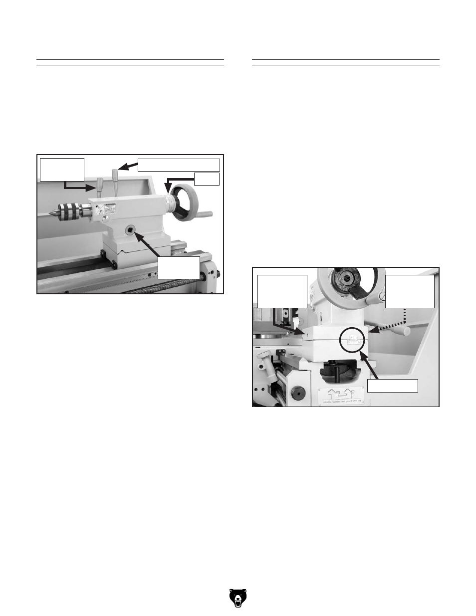
figure 37. tailstock off-set adjustments.
Front
Adjustment
screw
rear
Adjustment
screw
offset scale
Tailstock
Tailstock Lock Lever
When clamped in place, the forces draw a
tailstock down into alignment with the spindle cen-
terline. this distance is usually a few thousandths
of an inch. When a tailstock lock lever is tightened
by hand, the clamping pressure and tailstock
alignment can be inconsistent. to eliminate this
situation, a
1
⁄
2
" drive ft/lb torque wrench can be
inserted into the lock lever drive hub (see
figure
36). the tailstock then can be clamped in place
at a pre-determined torque setting. As a result, all
lathe operators can rely on the same draw-down
alignment.
Tailstock Handwheel
the tailstock handwheel includes a micrometer
collar in increments of 0.001"–0.100". rotating the
handwheel moves the quill at a 1:1 ratio with the
collar. one full handwheel rotation moves the quill
1
⁄
10
" for up to a maximum of 4" of travel. the quill
also has a metric scale from 1mm–100mm.
figure 36. tailstock controls.
1
⁄
2
" drive
hub
tailstock lock lever
Quill lock
lever
scale
Quill Lock Lever
the quill lock lever (see
figure 36) secures the
quill in its current position. When drilling, or when
tapping operations need to be done deep into a
part, the quill can also be stabilized by slightly
applying the lever to add drag and preload to the
quill.