Saddle gib, Compound slide gib – Grizzly G0709 User Manual
Page 64
-62-
Model G0709 (Mfg. Since 5/11)
Saddle Gib
the saddle is supplied with a carriage lock on the
front right-hand side of the slide (see
figure 99).
this bolt locks the saddle in place for increased
rigidity when making face cuts. Before making
adjustments to the saddle gib, make sure that this
lock is loose by turning it counterclockwise one
full turn.
IMpORTANT: Do not loosen the carriage lock
more than a couple of turns or the components
inside will come apart. Re-installing these compo-
nents is difficult and time consuming.
the saddle gib is located on the bottom of the
back edge of the slide (
figure 100). this gib is
designed differently than the cross or compound
slide gibs. instead of being a wedge-shaped
plate, it is a flat bar. the gib pressure is applied
by four set screws. hex nuts secure these set
screws in place, so they will not loosen during
operation.
Tools Needed
Qty
Wrench 10mm ................................................... 1
hex 3mm ........................................................... 1
hex 6mm ........................................................... 1
To adjust the saddle slide gib:
1. disConneCt lAthe FroM poWer!
2. Clean and lubricate the lathe ways, slide, and
leadscrew (refer to
ball Oiler Lubrication on
page 53 for instructions and lubricant specifi-
cations).
3. if the carriage lock (figure 87) is tight, loosen
it
two turns.
4. loosen the jam nuts on the four set screws
shown in
figure 100, and adjust the set
screws as follows:
—to tighten the carriage gib, tighten the set
screws.
—to loosen the gib, loosen the set screws.
5. repeat adjustments as necessary until the
carriage adjustment is acceptable.
6. hold the set screws in place and tighten the
jam nuts.
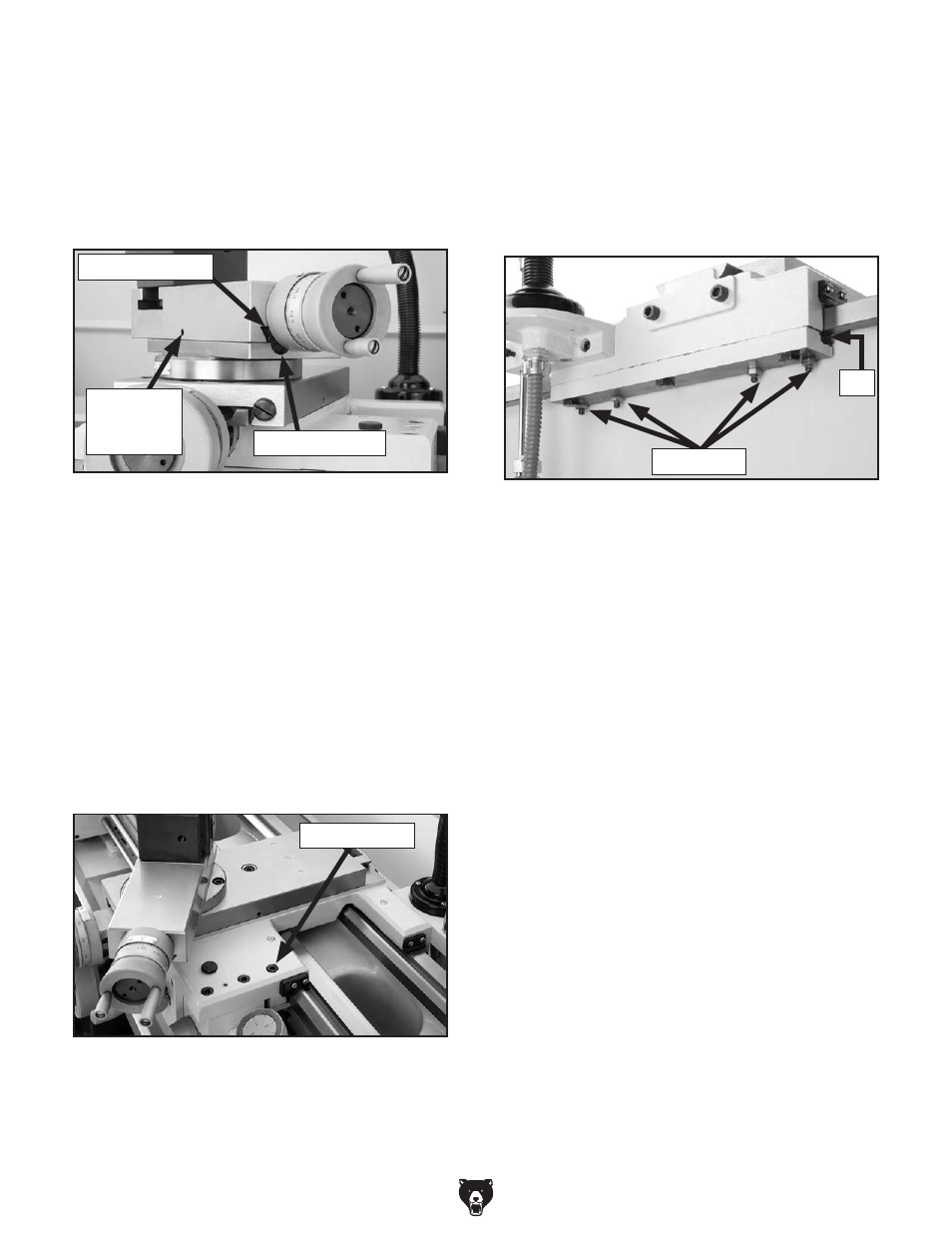
figure 100. saddle gib components.
set screws
gib
compound Slide Gib
figure 98 shows the gib arrangement for the
compound slide. the compound slide gib adjusts
in the same manner and with the same tools
as the cross slide gib. however, in this case, to
increase or decrease tension, the gib adjustment
screw directions are reversed.
figure 98. Compound slide gib components.
Front gib screw
Front end of gib
Compound
slide gib
lock
figure 99. location of carriage lock.
Carriage lock