Brake, Tailstock – Grizzly G0709 User Manual
Page 28
-26-
Model G0709 (Mfg. Since 5/11)
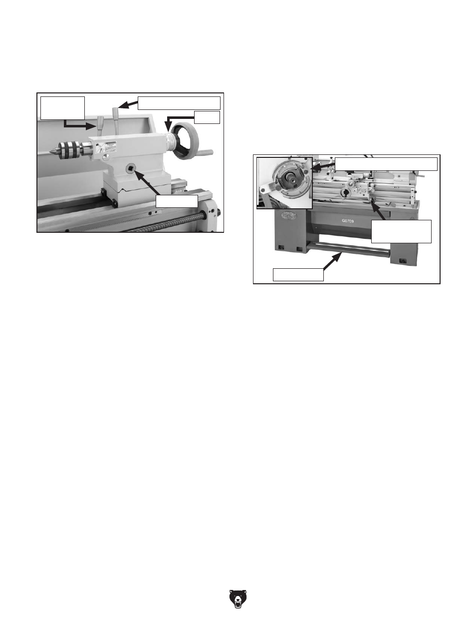
brake
When pressed, the brake pedal (see
figure 17)
actuates mechanical linkage that expands brake
shoes within the spindle drive pulley and stops
the lathe spindle. At the same time the motor
power supply circuit is cut by a linkage-controlled
limit switch. to resume lathe operations after the
brake has been used, return the spindle on/oFF
lever to the central position, and all lathe controls
become "live" again.
figure 17. spindle brake system.
Brake pedal
spindle
on/oFF lever
Brake shoes and linkage
Tailstock
figure 16. tailstock controls.
tailstock lock lever
Quill lock
lever
scale
Quill Lock Lever
secures the quill in a locked or pre-loaded posi-
tion.
Tailstock Lock Lever
Clamps the tailstock in place for general position
locking along the lathe bed.
Drive Hub
Allows the tailstock to be locked in place using a
1
⁄
2
" drive torque wrench to control amount of draw-
down alignment with the spindle centerline.
Tailstock Handwheel
Advances or retracts the quill in the tailstock
at a 1:1 ratio with the micrometer scale on the
handwheel hub.
Micrometer Scale
displays quill travel in increments of 0.001" with
a total rotation value of 0.100", (for every full rota-
tion of the handwheel, the quill moves
1
⁄
10
"). the
tailstock quill is broken down with an inch scale up
to 4" and a metric scale up to 100mm.
use the descriptions in this section and the con-
trols shown in
figure 16 to quickly understand the
functions of the tailstock controls.
drive hub