Control panels – Grizzly G0649 User Manual
Page 19
g0649 Welding downdraft table
-17-
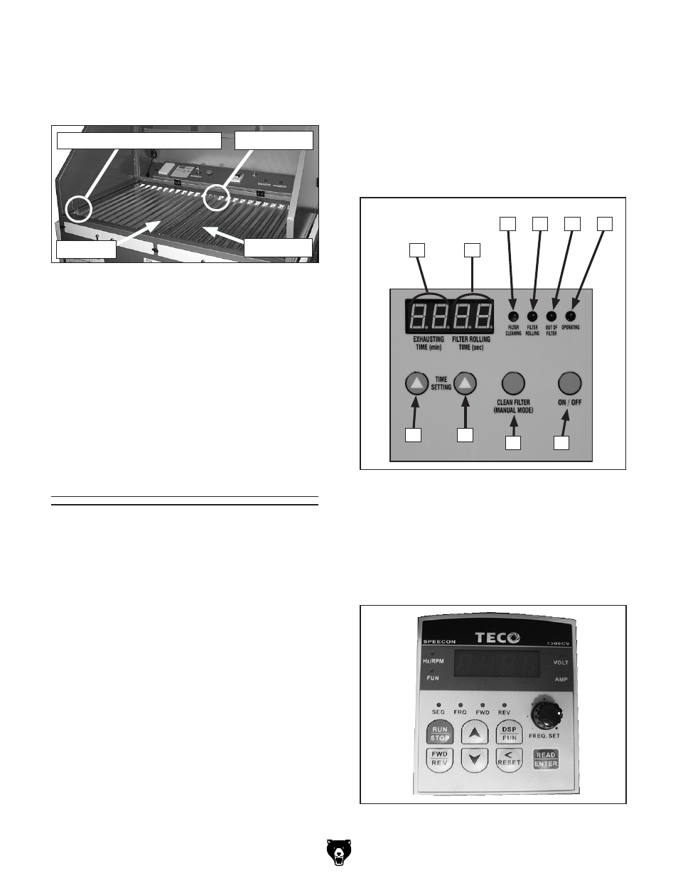
figure 8. Frequency drive control panel.
a
B
C
d
E
F
g
h
i
J
figure 7. digital control panel.
A. EXhAuSTinG TiME (min): displays in min-
utes, how much welding time is allotted
before new filter paper is exposed.
b. fiLTER ROLLinG TiME (sec): displays in
seconds, the duration of roller-filter advance.
c. fiLTER cLEAninG: lamp lights when the
vibrating-type filter is being de-caked.
D. fiLTER ROLLinG: lamp lights when the
roller-type filter is advancing.
E. OuT Of fiLTER: lamp lights when the
roller-type filter has run out and needs chang-
ing.
f. OPERATinG: lamp lights indicating that the
machine is running.
G. SETTinG TiME (Left button): allows for
changing the
EXhAuSTinG TiME.
control Panels
4. Connect welding ground cable to the ground
stud on the left-hand corner of the table and
make sure the ground strap is connecting
both left and right work tables (
figure 6).
h. SETTinG TiME (Right button): allows for
changing the
fiLTER ROLLinG TiME.
i. cLEAninG fiLTER (MAnuAL MODE)
button: When the machine is OFF, press
this button to de-cake vibrating filter.
J. On/Off button: toggles machine operation
ON and OFF.
K. fREQuEncy DRivE cOnTROL PAnEL:
allows you to adjust the fan motor supply
voltage frequency which in turn changes the
suction CFM. this is an important adjustment
if you want to maintain the flux gas atmo-
sphere around the point of welding.
figure 6. grounded welding work tables.
Welding Cable ground Stud
ground Strap
note: Under both work tables exists a plas-
tic frame that insulates the machine digital
circuitry from welding current fluctuations.
The ground strap shown above must con-
nect both left and right tables. If this ground
strap is missing, loose, or is disconnected,
and the welding cable ground is connected
to the welding ground stud, the right table
will be poorly grounded and be an insufficient
ground required for quality welding results.
left table
right table