Test run, Site considerations – Grizzly G0649 User Manual
Page 16
-14-
g0649 Welding downdraft table
Test Run
once you have assembled this machine com-
pletely, test run your machine to make sure it runs
properly.
if, during the test run, if you cannot easily locate
the source of an unusual noise or vibration, stop
using the machine immediately, then review the
Troubleshooting on Page 29.
if you still cannot remedy a problem, contact our
tech Support at (570) 546-9663 for assistance.
To test run the machine:
1. Make sure that all filters are properly posi-
tioned. refer to the
Maintenance section on
Page 22 if required.
2. push in and then rotate the emergency stop
button clockwise (
figure 5), so it pops out to
so it is positioned in the run position.
floor Load
refer to the
Machine Data Sheet for the weight
and footprint specifications of your machine.
Some floors may require additional reinforcement
to support both the machine and operator.
Placement Location
this machine is designed to operate when the
environment temperature is between 41°F to
122°F, and when the humidity is between 30%
to 95%. however, if the machine is only to be
use in cycles that are less than 24-hour runs and
allowed to cool between the runs, the maximum
ambient temperature range for operation can be
raised to 133°F.
Consider existing and anticipated needs, size
of material to be welded, and space for auxil-
iary stands, work tables or other machinery when
establishing a location for your new machine.
children and visitors may be
seriously injured if unsuper-
vised around this machine.
Lock entrances to the shop
or disable start switch or
power connection to prevent
unsupervised use.
Site considerations
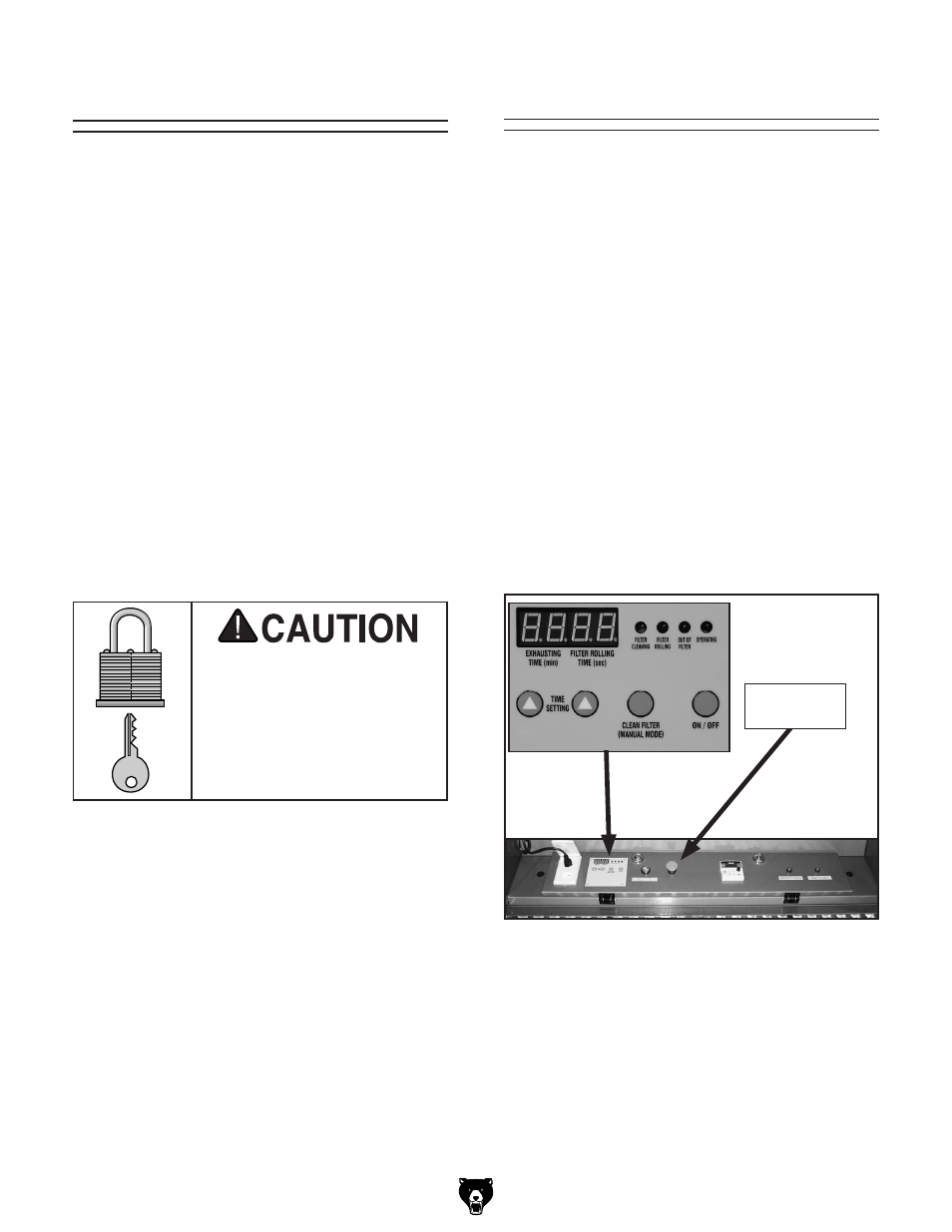
3. Connect the machine to the power source. the
EXhauSting tiME and FiltEr rolling
tiME digital displays (
figure 6) will be now
lit. the values shown on the displays are the
initial factory settings.
4. Make sure you have read the safety instruc-
tions at the beginning of the manual and that
the machine is setup properly.
figure 5. Control panel.
Emergency
Stop Button