Installation instructions, Site requirements, Gas supply – Stovax E-Studio PR0776 User Manual
Page 15: Ventilation, Appliance location
15
INSTAllATION INSTRUCTIONS
SITE REQUIREMENTS
TIMBER FRAMED BUIlDINGS
1.5 It will be necessary to provide additional clearance when
the flue passes through a wall containing any combustible
materials so as to prevent a fire hazard.
1.6 The hole through which the flue will pass, must have a steel
sleeve which is positioned so that an air gap of at least
25mm is maintained between the outer surface of the flue,
and any part of the sleeve.
1.7 For further guidance on the installation of gas appliances in
timber framed buildings, contact your local buildings control
authority.
2. GAS SUPPlY
2.1 Before installation, ensure that the local distribution
conditions (identification of the gas type and pressure) and
the adjustment of the appliance are compatible.
2.2 Ensure that the gas supply is capable of delivering the
required amount of gas, and is in accordance with the rules
in force.
2.3 Factory-sheathed/wrapped soft copper tubing with small
ridges which allow pipe movement are considered to be a
suitable alternative to a pipe sleeve, when recessing the unit
into a cavity wall the gas supply is best fed through the wall
from the outside. Soft soldered joints can only be used
outside the appliance.
2.4 This appliance is supplied complete with a factory fitted
isolation device incorporated into the inlet connection. No
further isolation device is therefore required.
3. vENTIlATION
3.1 This appliance requires no additional ventilation.
4. APPlIANCE lOCATION
NOTE: It is recommended you construct the back panel of the
fireplace from natural materials cut into three or more
sections to prevent cracking. Resin-based materials may
not be suitable. This appliance is an effective heat
producer and attention must be paid to the construction
and finish of the fireplace.
4.1 This appliance must stand on a non combustible hearth that
is at least 12mm thick. If the fire is greater than 50mm
above the floor, then no hearth is required, although due
consideration should be given to how the heat may affect
the floor material.
4
AR0184
A
B
C
D
E
F
DIMENSIONS
MIN
MAX
A
420 mm 450 mm
B
560 mm 575 mm
C
237 mm
-
D
300 mm
-
E
420 mm
-
F
12 mm
-
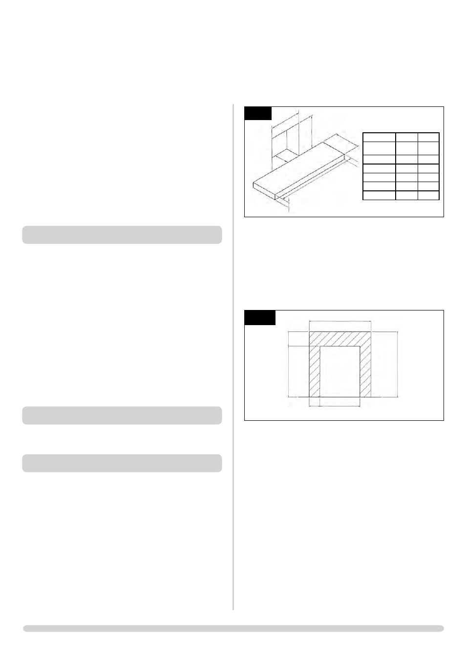
4.2 The minimum opening dimensions are shown, Diagram 4.
4.3 This appliance can only be installed on an outside wall with
suitable clearances for the flue terminal and guard (if
required).
4.4 This appliance is not suitable for installation into a
combustible wall. All combustible material must be
removed from the area shown, Diagram 5.
5
AR1227
720
420
150
560
300
860
4.5 The maximum depth of combustible shelf is 150mm at a
minimum height of 300mm above the fireplace opening.