Power connection – Grizzly G0651 User Manual
Page 32
-30-
model g0651/g0652 (mfg. since 1/10)
power connection
Before the machine can be connected to the
power source, an electrical circuit must be made
available that meets the minimum specifications
given in "Circuit requirements for 220v" on
page
15. if a power circuit has not been prepared for the
machine, do that now. to ensure a safe and code-
compliant setup, we strongly recommend that all
electrical work be done by a qualified electrician.
G0652 power connection
hardwire setups require power supply lines to be
enclosed inside conduit, which is securely mount-
ed and constructed in adherance to applicable
electrical codes.
a hardwire setup for this machine must be
equipped with a locking disconnect switch as a
means to disconnect the power during adjust-
ments or maintenance, which is a typical require-
ment for lock-out/tag-out safety programs (com-
monly required by osha).
Figure 3 on page 17 shows a simple diagram of
a hardwire setup with a locking disconnect switch
between the power source and the machine.
due to the complexity required for planning,
bending, and installing the conduit necessary for
a hardwire setup, this type of setup can only be
performed by an experienced electrician.
G0651 power connection
insert the pre-installed 6-15 plug into a matching
220v, nema 6-15 receptacle, similar to the one
shown in
Figure 2 on page 16.
To connect the Model G0652 to 220V/440V
power:
1. remove the junction box cover on the rear of
the cabinet.
2. loosen the strain relief on the bottom of the
junction box shown in
Figure 33, then insert
the incoming power wires into the junction
box.
Figure 33. power connection junction box.
strain relief
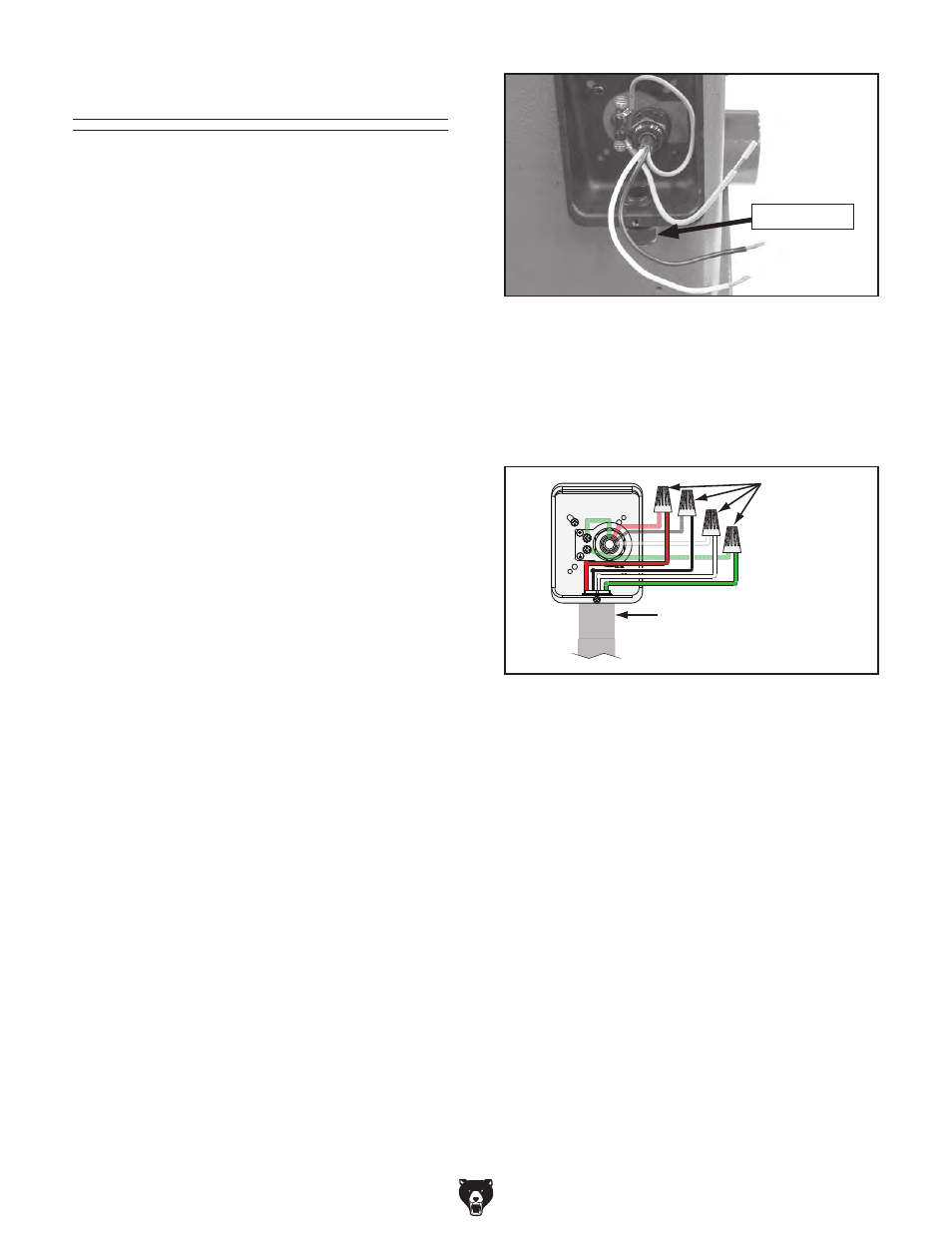
3. Connect the incoming power wires and
ground wire to the wires in the junction box
using wire nuts, (see
Figure 34), then wrap
each of the wire nuts and their respective
wires with electrical tape to secure them.
>cXdb^c\
EdlZgA^cZ
8dccZXi
L^gZh
l^i]
L^gZ
Cjih
Figure 34. model g0652 incoming power wires
connected at junction box.
4. tighten the strain relief on the bottom of the
junction box against the conduit—not directly
against the wires—then re-install the cover.
leave a little slack in the wires inside the
junction box.
phase converter precaution
the power from the manufactured leg may dam-
age electrical components if connected to the
wrong incoming power terminal on your machine.
refer to the phase converter notice on the wiring
diagram on
page 86 for more detail.