10 removing the internal speakers, Maintenance & disassembly – FIC A360 User Manual
Page 133
Maintenance & Disassembly
2. To remove the top cover, you need to remove several screws. There are ten screws found
on the top cover as indicated on the figure previous page. Remove them all.
3. Slowly unsnap the top cover from the system cover. Release one cable connected from
the RTC battery to the main board and the other cable connected from the internal
microphone to the main board. Then pull out the top cover.
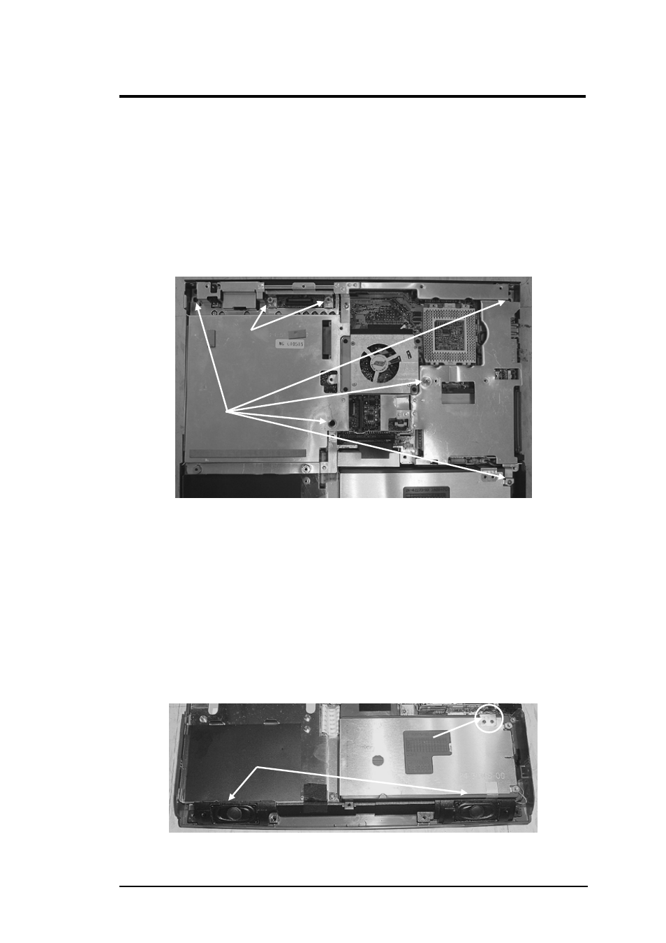
4. Then to remove the system cover, you need to remove several screws. There are five
screws and two hex bolts found on the system cover as indicated on the figure below.
Remove them all.
Two
Hex
Bolts
Screws
Figure 5-15
System Cover Screw Locations
5. Release one cable connected from the fan to the main board and notice a rubber foot of
fan module. Then Slowly unsnap the system cover from the bottom case.
5.5.10 Removing the Internal Speakers
The internal speakers are connected on the front side of the base unit assembly. They are
connected to the main board using wire cable. Follow the procedures below and illustration
on how to remove the panel:
1. Before removing the internal speaker module, you need first to disassemble keyboard,
palm rest, HDD, LCD panel, heat sink plate, CD-ROM, top cover, and system cover.
Internal
Speaker
Connector
Figure 5-16
Internal Speaker Assembly
FIC A360 Service Manual 5-13