FUJITSU DISK DRIVES MHM215OAT User Manual
Page 128
5.3 Host Commands
C141-E104-02EN
5-51
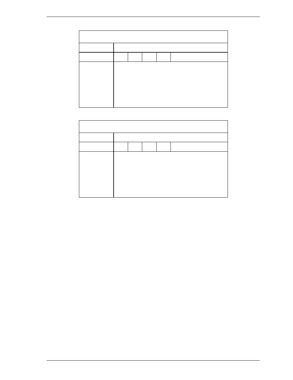
At command issuance (I/O registers setting contents)
1F7
H
(CM)
1
1
1
1
1
0
0
0
1F6
H
(DH)
x
L
x
DV
xx
1F5
H
(CH)
1F4
H
(CL)
1F3
H
(SN)
1F2
H
(SC)
1F1
H
(FR)
xx
xx
xx
xx
xx
At command completion (I/O registers contents to be read)
1F7
H
(ST)
Status information
1F6
H
(DH)
x
x
x
DV
Max head/LBA [MSB]
1F5
H
(CH)
1F4
H
(CL)
1F3
H
(SN)
1F2
H
(SC)
1F1
H
(ER)
Max. cylinder [MSB]/Max. LBA
Max. cylinder [LSB]/Max. LBA
Max. sector/Max. LBA [LSB]
xx
Error information
(18) EXECUTE DEVICE DIAGNOSTIC (X’90’)
This command performs an internal diagnostic test (self-diagnosis) of the device.
This command usually sets the DRV bit of the Drive/Head register is to 0
(however, the DV bit is not checked). If two devices are present, both devices
execute self-diagnosis.
If device 1 is present:
•
Both devices shall execute self-diagnosis.
•
The device 0 waits for up to 5 seconds until device 1 asserts the PDIAG-
signal.
•
If the device 1 does not assert the PDIAG- signal but indicates an error, the
device 0 shall append X’80’ to its own diagnostic status.
•
The device 0 clears the BSY bit of the Status register and generates an
interrupt. (The device 1 does not generate an interrupt.)
•
A diagnostic status of the device 0 is read by the host system. When a
diagnostic failure of the device 1 is detected, the host system can read a status
of the device 1 by setting the DV bit (selecting the device 1).