Microtech communication port configuration, 3 microtech communication port configuration, Bacdrop – FieldServer FS-8700-80 User Manual
Page 11: Legend
McQuay Micro Tech Open Protocol Driver Manual
Page 11 of 43
FieldServer Technologies 1991 Tarob Court Milpitas, California 95035 USA Web: www.fieldserver.com
Tel: (408) 262 2299 Fax: (408) 262 2269 Toll Free: (888) 509 1970 email: [email protected]
1.3
MicroTech Communication Port Configuration
In addition to the rules about MicroTech architecture and addressing, there is also a critical parameter called the
Comm Port Configuration. The Comm Port Configuration must also be set correctly for a unit controller to be able
to communicate. This comm port configuration for level 1 devices is different to level 2 devices. While it is
necessary to know this for proper unit controller setup and for troubleshooting communication problems, it is not
critical from the FieldServer side for programming or routing.
A level 1 device must have its communication port configuration set up as “Level 1 TTY/Slave”. To change this
configuration, connect to the unit controller with MicroTech Monitor software through the “A” port, proceed to
the “Read/Write” screen, read memory address “0A11”, and change the value to “C1” (Level 1 TTY/Slave). After
doing this, the controller must also have its rotary hex switches set to the Level 1 address of “00” to make the unit
controller’s network address 00.00. Please note that power must be cycled to the controller for this new hex
switch setting to take effect.
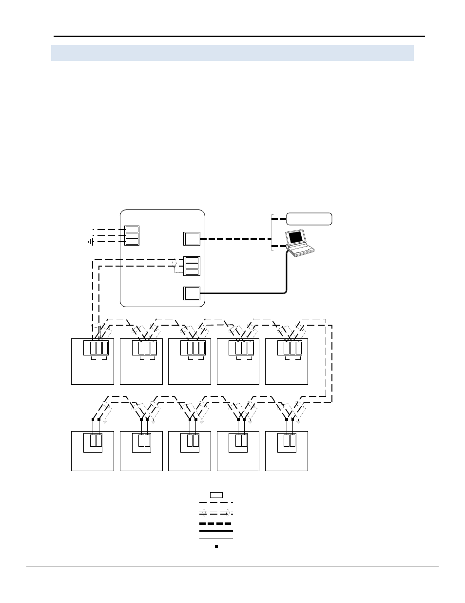
Figure 6. MicroTech Network with BACdrop Panel as Level 1 Device
T
S
2
BACdrop
Hot
Neutral
100 – 240 Vac
Power
L2
L1
GRD
Notes:
1. Twisted, shielded pair cable must meet the following
minimum requirements: 300 V, 60°C, 20 AWG, polyethylene
insulated, with a PVC outer jacket and drain wire (Belden
8762 or equivalent). Some local codes may require the use
of plenum rated cable.
2. 10BaseT Ethernet cable. To directly connect a PC to the
Ethernet port, a hub or a special crossover cable must be
used.
3. Cable length must not exceed 5000 ft (1524 m).
4. Standard serial cable. A null modem is not required.
S
e
e
n
o
te
s
1
&
3
S
e
lf-
co
n
ta
in
e
d
A
C
P
o
rt
B
G
N
D
T
B
7
R
e
ci
p
ro
ca
tin
g
ch
ill
e
r
P
o
rt
B
1
3
9
T
B
4
S
cr
e
w
c
h
ill
e
r
P
o
rt
B
55
BLK
WHT
B+
B–
1
3
8
1
3
7
54
53
C
o
m
m
B
U
V
C
(
3
2
5
)
1
2
P
N
K
G
R
Y
C
o
m
m
B
U
V
C
(
1
2
5
)
4
5
P
N
K
G
R
Y
RJ-45
3rd-party BAS
See note 2
T
B
1
C
e
n
tr
ifu
g
a
l c
h
ill
e
r
(s
e
rie
s 2
0
0
)
P
o
rt
B
85
86
84
T
B
2
A
p
p
lie
d
r
o
o
ft
o
p
P
o
rt
B
1
3
0
1
2
8
1
2
9
Legend
Field wiring terminal
Field wiring: discrete
Factory wiring
Field wiring: twisted, shielded pair cable
with drain wire
(see note 1)
B+
Crimp or solder splice
BLK
WHT
BLK
WHT
BLK
WHT
BLK
WHT
BLK
WHT
BLK
WHT
BLK
WHT
BLK
WHT
BLK
WHT
C
o
m
m
B
U
V
C
(
3
2
5
)
1
2
P
N
K
G
R
Y
C
o
m
m
B
U
V
C
(
3
2
5
)
1
2
P
N
K
G
R
Y
C
o
m
m
B
U
V
C
(
3
2
5
)
1
2
P
N
K
G
R
Y
Ethernet
DB9
PC
PC
+
–
GRD
Network
See note 4
Field wiring: 10BaseT Ethernet
Standard serial cable