Dimensions, Wall sleeve attachment – Friedrich 920-087-09 (12/10) User Manual
Page 8
8
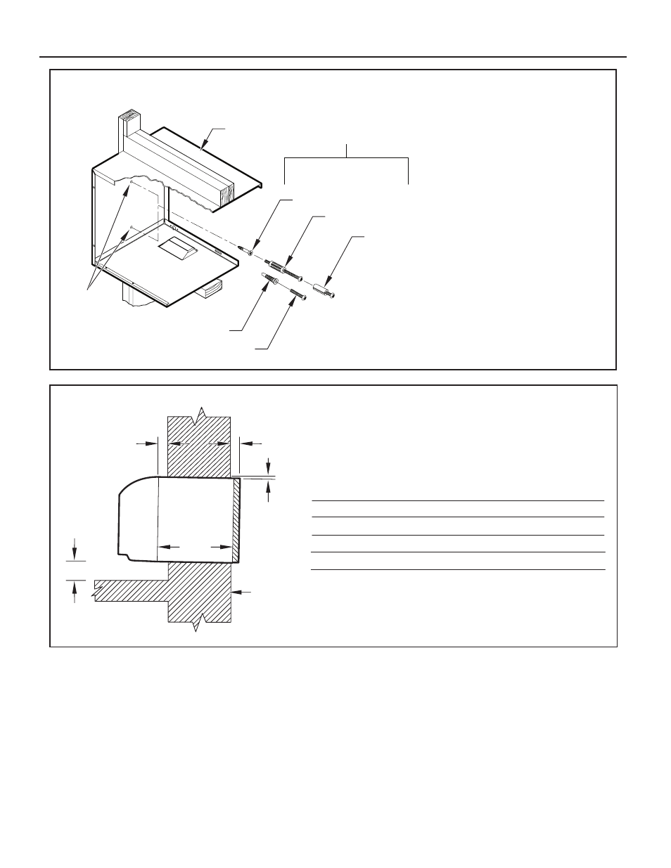
Figure 9
Dimensions
FRP007
NOTE: The Wall Sleeve must be
horizontally level (side-to-side)
and pitched 1/4 bubble to the
outside when installed in an
opening.
The mounting hole location
should be approximately 2-4”
from the top and bottom of the
sleeve.
MOUNTING
HOLES
PLASTIC ANCHORS
WOOD SCREW
ALTERNATE
FASTENING METHODS
(Field Supplied)
TOGGLE BOLT
EXPANSION
ANCHOR BOLT
SCREWS
WALL
SLEEVE
Figure 8
Wall Sleeve Attachment
FRP009
¼"
13-¾"
A
C
B
Dimension*
A
B
Allow
for floor
finishing
Allow
for wall
finishing
(Minimum)
Min. Max.
No Accessories
¼"
MIN.
WALL
¼"
---
With Subbase
1-¾"
3-½"
5"
With Lateral Duct
¾"
C
Allow
for proper
drainage
(Front-to-Back)
¼"
---
---
---
---
* If more than one accessory is to be used, use the maximum
dimension. If the wall thickness is more than 13-¾" - (A+ ¼"),
a sleeve extension must be used.
Wall Sleeve Tilt
¼"
---
---
---
- 7,200 BTU Packaged Terminal Air Conditioner Warranty 7,200 BTU Packaged Terminal Air Conditioner Installation and Operation Manual ZoneAire Series 42 Inch Packaged Terminal Air Conditioner Warranty A-SERIES 24,000 BTU/h 9 HEAT PUMPS 7,200 BTU Packaged Terminal Air Conditioner Product Profile ZoneAire Series 42 Inch Packaged Terminal Air Conditioner Warranty Guide ZoneAire Series 42 Inch Packaged Terminal Air Conditioner Installation Guide ZoneAire Series Electric Heat Packed Terminal Air Conditioner Installation Manual ZoneAire Series 14,500 BTU Smart Packaged Terminal Air Conditioner Installation Guide 12,000 BTU FreshAire® Package Terminal Air Conditioner Installation Manual