Notice, Detail b detail a, Drain tube installation (see figure 12) – Friedrich 920-087-09 (12/10) User Manual
Page 11: Cover plate installation, Drain kit installation
11
FRP012
FOAM
GASKET
OVERFLOW
SLOTS
DETAIL B
DETAIL A
COVER
PLATE
FOAM
GASKET
SCREWS
½” O.D. TUBE
MOUNTING
PLATE
NUT
External Drain (for new
construction or unit replacement)
When.using.an.external.drain.system,.the.condensate.is.removed.through.
either.of.two.drain.holes.on.the.back.of.the.wall.sleeve...Select.the.drain.
hole.which.best.meets.your.drainage.situation.and.install.the.drain.kit..
Seal.off.the.other.with.a.cover.plate.
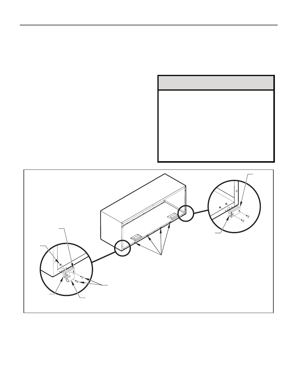
Drain Tube Installation (See Figure 12)
1. Peel.the.backing.tape.off.the.gaskets.and.apply.the.sticky.side.
to.one.cover.plate.and.one.mounting.plate.as.shown.in.Details.
A.and.B.
2. Place.the.drain.tube.through.the.gasket.and.the.mounting.plate.
with.the.flange.toward.the.wall.sleeve.
3. Attach.the.drain.tube.assembly.to.one.of.the.two.drain.holes.at.the.
rear.of.the.wall.sleeve...The.large.flange.on.the.mounting.plate.is.
positioned.at.the.bottom.of.the.sleeve.facing.toward.the.sleeve,.
Detail.B...When.the.drain.tube.is.positioned.at.the.desired.angle,.
tighten.the.screws..
Cover Plate Installation
4. Mount.the.foam.gasket.to.the.cover.plate...Using.two.#10.x.½".sheet.
metal.screws.(provided),.attach.the.cover.plate.to.the.remaining.
drain.hole...Make.certain.the.large.flange.on.the.plate.is.positioned.
at.the.bottom.of.the.sleeve.
5. Discard.the.additional.cover.plate,.gasket,.machine.screws,.and.
locknuts.
NOTE:.
The.large.flange.on.the.mounting.plate.is.positioned.at.the.bottom.of.the.sleeve.facing.toward.the.sleeve...The.drain.tube.must.be.rotated.to.a.
horizontal.position.to.allow.for.the.wall.sleeve.to.be.installed.into.the.wall...Once.the.wall.sleeve.is.installed,.return.the.drain.tube.to.a.downward.
angle.
Figure 12
Drain Kit Installation
NOTICE
If the wall sleeve has not been installed, the drain tube
must be rotated to a horizontal position until after the
sleeve is installed. Tighten the mounting plate screws
when the tube is in the proper position. Make certain that
the four overflow slots at the rear of the wall sleeve are not
blocked (See Figure 12).
When sealing the sleeve on the outside of the building, be
careful NOT to let the sealant block the two condensate
drain holes or the four overflow slots at the bottom flange
of the sleeve.
Potential property damage can occur if instructions are
not followed.
- 7,200 BTU Packaged Terminal Air Conditioner Warranty 7,200 BTU Packaged Terminal Air Conditioner Installation and Operation Manual ZoneAire Series 42 Inch Packaged Terminal Air Conditioner Warranty A-SERIES 24,000 BTU/h 9 HEAT PUMPS 7,200 BTU Packaged Terminal Air Conditioner Product Profile ZoneAire Series 42 Inch Packaged Terminal Air Conditioner Warranty Guide ZoneAire Series 42 Inch Packaged Terminal Air Conditioner Installation Guide ZoneAire Series Electric Heat Packed Terminal Air Conditioner Installation Manual ZoneAire Series 14,500 BTU Smart Packaged Terminal Air Conditioner Installation Guide 12,000 BTU FreshAire® Package Terminal Air Conditioner Installation Manual