Digital control user input configuration, Dip switch, Dip switches – Friedrich 920-087-09 (12/10) User Manual
Page 23: Dip switch setting
23
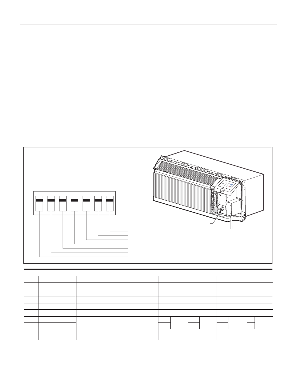
The.adjustable.control.dip.switches.are.located.at.the.lower.left.hand.portion.of.the.digital.Smart.Center..The.inputs.are.only.visible.and.accessible.with.the.
front.cover.removed.from.the.PTAC.
Digital Control User Input Configuration
Switch
Description
Function
Factory Setting
Option
1
Emergency.Heat.Override.
for.PDH.Heat.Pump.
Models
Enables.electric.heat.only.operation.in.the.event.of.a.com-
pressor.failure.on.HP.models.
Down.-.Normal.Operation
Up.-.Overrides.compressor.operation..
(PDH.models.only)
2
Wall.Thermostat.Switch
Enables.the.use.of.a.wall.thermostat.or.unit.controls
Down.-.Unit.Controls
Up.-.Enables.Wall.Thermostat.Usage
3
Fan.Cycle.for.Heating
Allows.selection.of.continuous.fan.or.cycling.in.heating.mode.
Down.-.Cycle
Up.-.Continuous
4
Fan.Cycle.for.Cooling
Allows.selection.of.continuous.fan.or.cycling.in.cooling.mode.
Down.-.Continuous
Up.-.Cycle
5
Setpoint.Switch.1
Allows.the.temperature.setpoint.range.to.be.adjusted.
Down
61F-86F
Up
63F-80F
Down 65F-78F
Up 68F-75F
6
Setpoint.Switch.2
Down
(16C-30C) Down (18C-28C) Up
(19C-26C)
Up (20C-24C)
7
Room.Freeze.Protection
Allows.the.unit.to.ensure.the.indoor.room.temperature.does.
not.fall.below.40F.even.when.turned.off.
Down.-.Freeze.Protection.Enabled
Up.-.Freeze.Protection.Disabled
FRP028
DIP SWITCH
LOCATION OF
DIP SWITCHES
ON UNIT
1
2
3
4
5
6
7
Freeze guard
Setpoint Limit 2
Setpoint Limit 1
Fan CON/CYC for cooling
Fan CON/CYC for heating
Wall Thermostat enable
Electric heat only (for Heat Pumps)
UP
DOWN
High
Med
Low
Fan
Cool
Heat
Fan Spee
d
Mode
Temperature
Power
Figure 31
Dip Switches
1. Emergency Heat Override – Switch 1
In.the.unlikely.event.of.a.compressor.failure.a.heat.pump.unit.may.
be.switched.to.operate.in.only.the.electric.heat.mode.until.repairs.
can.be.made..Moving.Dip.Switch.1.to.‘ON’.
2. Wall Thermostat Switch 2
In.order.to.enable.the.wall.thermostat.move.Dip.Switch.to.'ON'.
3. Fan Cycle Control – Switch 3-4
All.PTACs.are.shipped.from.the.factory.with.Dip.Switch.3-4.in.
the.‘OFF’.position...In.this.position.the.cooling.fan.cycle.will.run.
continuously.providing.air.circulation.during.the.warm.months...
The.heating.fan.cycle.is.set.to.'cycle'.on.and.off...The.fan.may.
be.set.to.'continuous'.mode.by.switching.Dip.Switch.3.to.'ON'.
position.
4. Electronic Temperature Limiting – Switches 5-6
The.digital.control.is.set.from.the.factory.to.allow.a.temperature.
range.between.61°.F.and.86°.F.in.both.heating.and.cooling.
mode..Dip.Switches.5-6.can.be.used.to.set.high.and.low.limits.for.
either.heating.both,.cooling.both.or.both.
From.the.factory.switches.are.in.the.down.'OFF'.position..The.
chart.below.shows.the.available.electronic.limiting.ranges.
5. Room Freeze Protection – Switch 7
Units.are.shipped.from.the.factory.with.the.room.freeze.protection.
enabled...Room.Freeze.Protection.can.be.switched.off.at.the.
owner’s.preference.by.moving.Dip.Switch.7.to.‘OFF’..This.feature.
will.monitor.the.indoor.room.conditions.and.in.the.event.that.the.
room.falls.below.40°F.the.unit.will.cycle.on.high.fan.with.the.
electric.heater..This.occurs.regardless.of.mode.
Dip Switch Setting
- 7,200 BTU Packaged Terminal Air Conditioner Warranty 7,200 BTU Packaged Terminal Air Conditioner Installation and Operation Manual ZoneAire Series 42 Inch Packaged Terminal Air Conditioner Warranty A-SERIES 24,000 BTU/h 9 HEAT PUMPS 7,200 BTU Packaged Terminal Air Conditioner Product Profile ZoneAire Series 42 Inch Packaged Terminal Air Conditioner Warranty Guide ZoneAire Series 42 Inch Packaged Terminal Air Conditioner Installation Guide ZoneAire Series Electric Heat Packed Terminal Air Conditioner Installation Manual ZoneAire Series 14,500 BTU Smart Packaged Terminal Air Conditioner Installation Guide 12,000 BTU FreshAire® Package Terminal Air Conditioner Installation Manual