Electrical wiring for 265 volt models, Warning, Electrical shock hazard – Friedrich 920-087-09 (12/10) User Manual
Page 14: Power cord installation
14
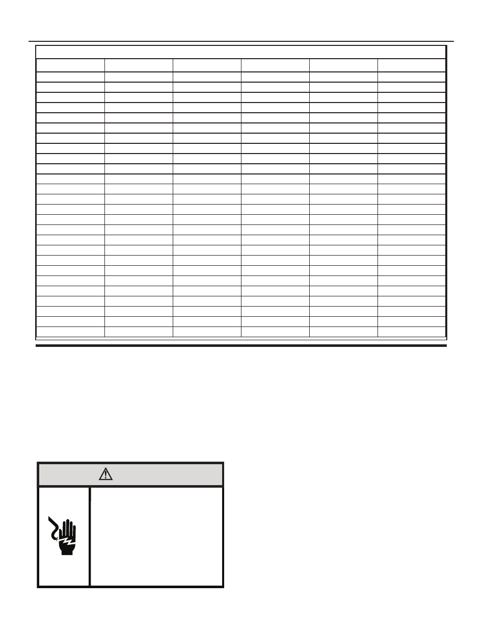
TABLE 2
Model
Heater kW
Power Cord Kit
Voltage
Amperage
Receptacle
PDE07K
0.0
PXPC23000
230/208
15
NEMA.6-15r
PDE/PDH07K
2.0
PXPC23015
230/208
15
NEMA.6-15r
3.0
STD
230/208
20
NEMA.6-20r
PDE09K
0.0
PXPC23000
230/208
15
NEMA.6-15r
PDE/PDH09K
2.0
PXPC23015
230/208
15
NEMA.6-15r
3.0
STD
230/208
20
NEMA.6-20r
5.0
PXPC23030
230/208
30
NEMA.6-30r
PDE12K
0.0
PXPC23000
230/208
15
NEMA.6-15r
PDE/PDH12K
2.0
PXPC23015
230/208
15
NEMA.6-15r
3.0
STD
230/208
20
NEMA.6-20r
5.0
PXPC23030
230/208
30
NEMA.6-30r
PDE15K
0.0
PXPC23000
230/208
15
NEMA.6-15r
PDE/PDH15K
2.0
PXPC23015
230/208
15
NEMA.6-15r
3.0
PXPC23020
230/208
20
NEMA.6-20r
5.0
STD
230/208
30
NEMA.6-30r
PDE/PDH07R
2.0
PXPC26515
265
15
NEMA.6-15r
3.0
STD
265
20
NEMA.6-20r
PDE/PDH09R
2.0
PXPC26515
265
15
NEMA.6-15r
3.0
STD
265
20
NEMA.6-20r
5.0
PXPC26530
265
30
NEMA.6-30r
PDE/PDH12R
2.0
PXPC26515
265
15
NEMA.6-15r
3.0
STD
265
20
NEMA.6-20r
5.0
PXPC26530
265
30
NEMA.6-30r
PDE/PDH15R
2.0
PXPC26515
265
15
NEMA.6-15r
3.0
PXPC26520
265
20
NEMA.6-20r
5.0
STD
265
30
NEMA.6-30r
Electrical Wiring for 265 Volt
Models
NOTE:.
It.is.recommended.that.the.PXSB.subbase.assembly,.the.
PXCJA.conduit.kit.(or.equivalent).be.installed.on.all.hardwire.
units...If.installing.a.flush-floor.mounted.unit,.make.sure.the.
chassis.can.be.removed.from.the.sleeve.for.service.and.
maintenance.
WARNING
Electrical Shock Hazard
Turn off electrical power before service
or installation.
ALL electrical connections and wiring
MUST be installed by a qualified
electrician and conform to the National
Code and all local codes which have
jurisdiction.
Failure to do so can result in property
damage, personal injury and/or death.
Power Cord Installation
All.265V.PTAC/PTHP.units.come.with.a.factory.installed.non-LCDI.
power.cord.for.use.in.a.subbase..If.the.unit.is.to.be.hard-wired.refer.to.
the.instructions.below.
To install the line voltage power leads and conduit
to chassis, follow the instructions below and refer
to Figures 25-27 on page 19. PXCJA Conduit Kit
is required with this setup.
1. Follow. the. removal. process. of. the. chassis’s. junction. box..
(Figure.25,.step.2,.page.19).
2. .Prepare.the.265V.(or.230V).power.cord.for.connection.to.the.chas-
sis’.power.cord.connector.by.cutting.the.cord.to.the.appropriate.
length.(refer.to.Figure.26.and.follow.Figure.15)...Power.cord.harness.
selection.shown.on.Table.2.on.page.14.
- 7,200 BTU Packaged Terminal Air Conditioner Warranty 7,200 BTU Packaged Terminal Air Conditioner Installation and Operation Manual ZoneAire Series 42 Inch Packaged Terminal Air Conditioner Warranty A-SERIES 24,000 BTU/h 9 HEAT PUMPS 7,200 BTU Packaged Terminal Air Conditioner Product Profile ZoneAire Series 42 Inch Packaged Terminal Air Conditioner Warranty Guide ZoneAire Series 42 Inch Packaged Terminal Air Conditioner Installation Guide ZoneAire Series Electric Heat Packed Terminal Air Conditioner Installation Manual ZoneAire Series 14,500 BTU Smart Packaged Terminal Air Conditioner Installation Guide 12,000 BTU FreshAire® Package Terminal Air Conditioner Installation Manual