Frymaster H50 Series User Manual
Page 98
2-35
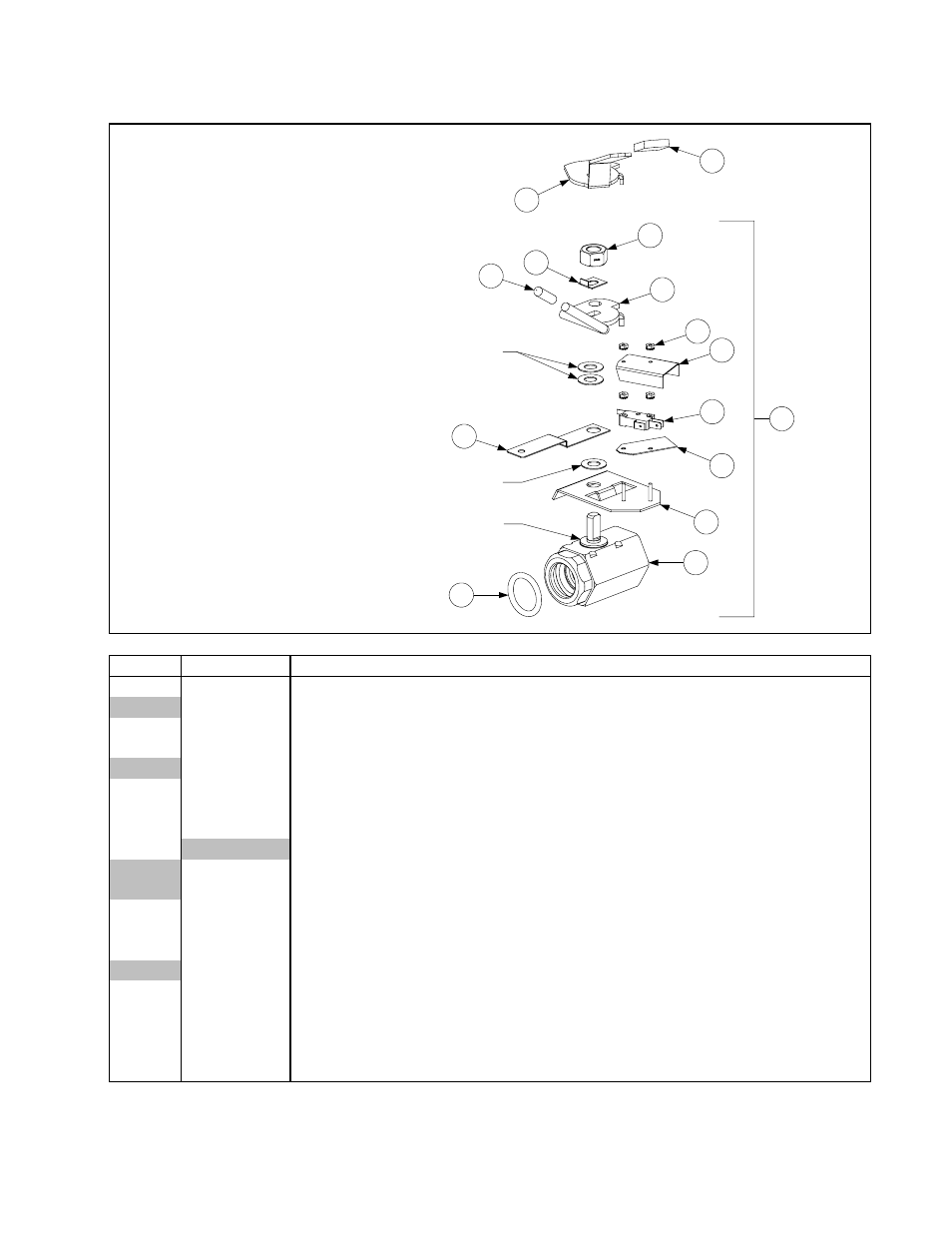
2.12.6 FPH50 Full Vat (1¼-inch) Valve Assemblies
Compression Washers
(part of Item 1)
Steel Flat Washer
(part of Item 1)
2
3
1
Plastic Washer
(part of Item 1)
4
5
6
7
8
9
10
11
12
13
14
15
N O T E : Co m p r e s s i on
washers must be turned
face to face and lock nut
(Item 13) must be torqued
to 80 ± 10 inch-pounds.
ITEM
PART #
COMPONENT
1
806-6373SP
Complete Assembly (for CE, use 806-6610SP)
806-6054
Valve Assembly, 1 ¼-inch Left Single FP
2
816-0135
O-Ring, Drain Valve, 1¼-inch I.D.
3
810-1018
Drain Valve, 1¼-inch NPT Inlet, 1-inch O-Ring Outlet, ½-inch Stem, FV
810-1020
Drain Valve, 1 ¼-inch NPT Inlet, 1-inch O-Ring Outlet, Single FP
4
806-8137
Bracket, Drain Valve, Microswitch
5
816-0220
Insulation, RF Switch
6
807-2103
Microswitch
7
Cover, Drain Safety Switch
900-2841
Used w/806-6373SP (Item 1)
901-2348
Replaces 900-2841 in 806-6610SP)
8
826-1366
Nut, Keps, 4–40, w/external teeth (Pkg. of 25)
9
900-2354
Bracket, Drain Valve, 1¼-inch
10
823-2371
Handle, Drain Valve (used w/806-6373SP) (replaced with 900-2609)
823-2066
Handle, Drain Valve Single FP
11
810-0677
Grip, Plastic Handle
12
900-2936
Retainer, FV Drain Valve Nut
13
809-0540
Nut, 2-way Lock, ½–13 (replaces nut that comes with 810-1018)
14
900-2609
Handle, Drain Valve (replaces Item 10 in 806-6610SP)
15
814-0047
Sleeve, Red Valve Handle