Frymaster H50 Series User Manual
Page 97
2-34
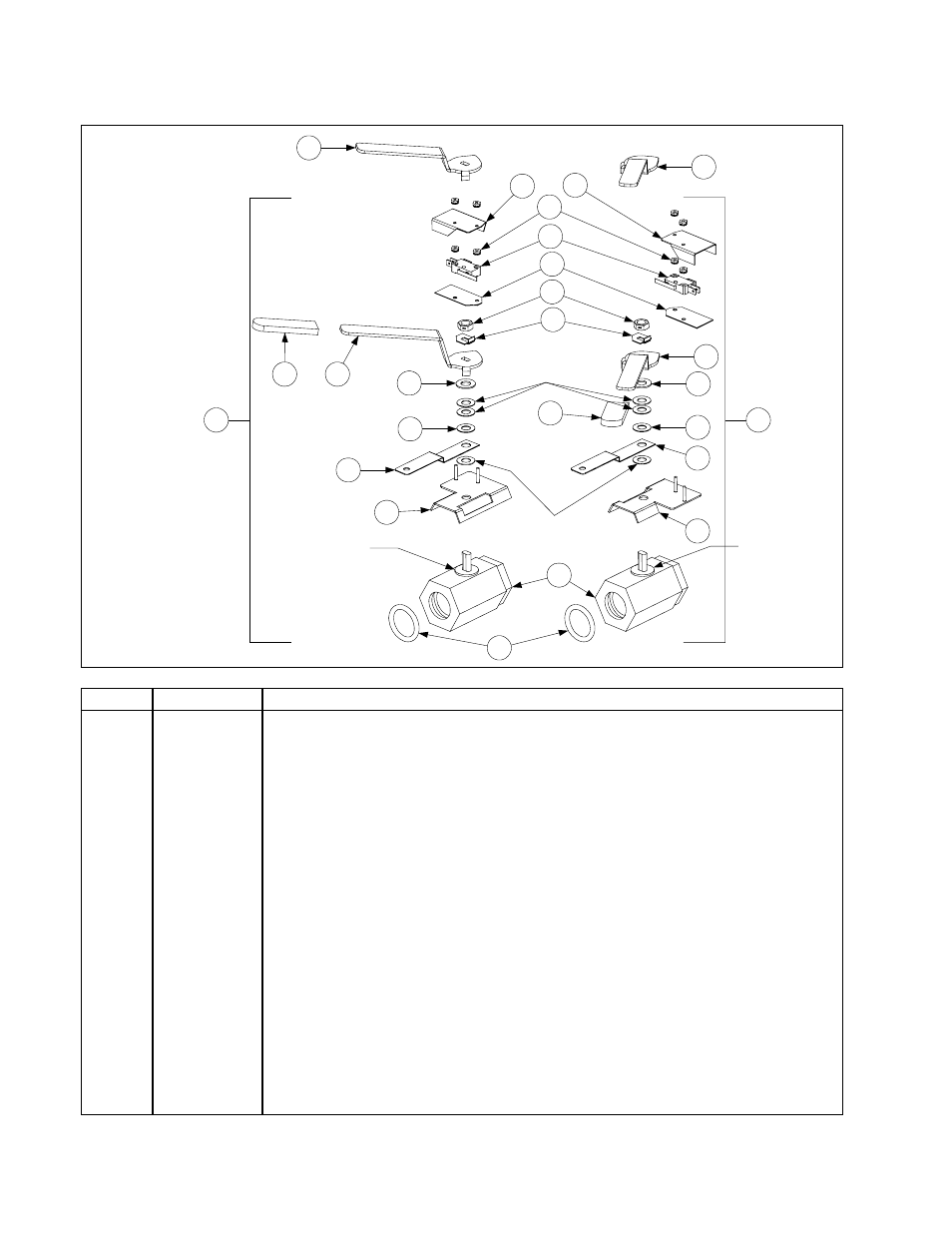
2.12.5 FPH50 Dual Vat (1-Inch X 1¼-inch) Valve Assemblies
3
1
2
4
Steel Flat Washer
(part of Item 4)
6
5
8
8
Compression
Washers
(part of Item 4)
17
14
9
9
10
7
7
Plastic Washer
(part of Item 4)
11
12
13
14
15
16
18
19
20
Plastic Washer
(part of Item 4)
N O TE : Co m p re s s i on
washers must be turned
face to face and lock nut
(Item 16) must be torqued
to 60 ± 10 inch-pounds.
21
ITEM
PART #
COMPONENT
1
806-6400SP
Complete Assembly, Left (for CE, use 806-6609SP)
2
806-6401SP
Complete Assembly, Right (for CE, use 806-6608SP)
3
816-0135
O-Ring, Drain Valve, 1”
4
810-1114
Drain Valve, 1¼-inch NPT Inlet, 1-inch O-Ring Outlet, ⅜-inch Stem
5
106-2671
Bracket, Drain Valve, Microswitch, Left
6
106-2672
Bracket, Drain Valve, Microswitch, Right
7
900-2355
Bracket, Drain Valve, 1-inch
8
810-1165
Washer, Teflon
10
201-3916
Handle, Drain Valve, Left
11
200-4304
Handle, Drain Valve, Right
12
201-3985
Handle, Drain Valve, Left (replaces Item 10 in 806-6609SP)
13
200-4305
Handle, Drain Valve, Right (replaces Item 11 in 806-6608SP)
14
814-0047
Sleeve, Red Valve Handle
15
900-2934
Retainer, ⅜-inch Nut
16
809-0539
Nut, 2-way Lock, ⅜ –16
17
816-0220
Insulation, RF Switch
18
807-2103
Microswitch, Lever Activated
19
826-1366
Nut, Keps, 4–40, w/external teeth (Pkg. of 25)
20
901-2348
Cover, Drain Safety Switch Left
21
902-2348
Cover, Drain Safety Switch Right