Frymaster H50 Series User Manual
Page 114
2-51
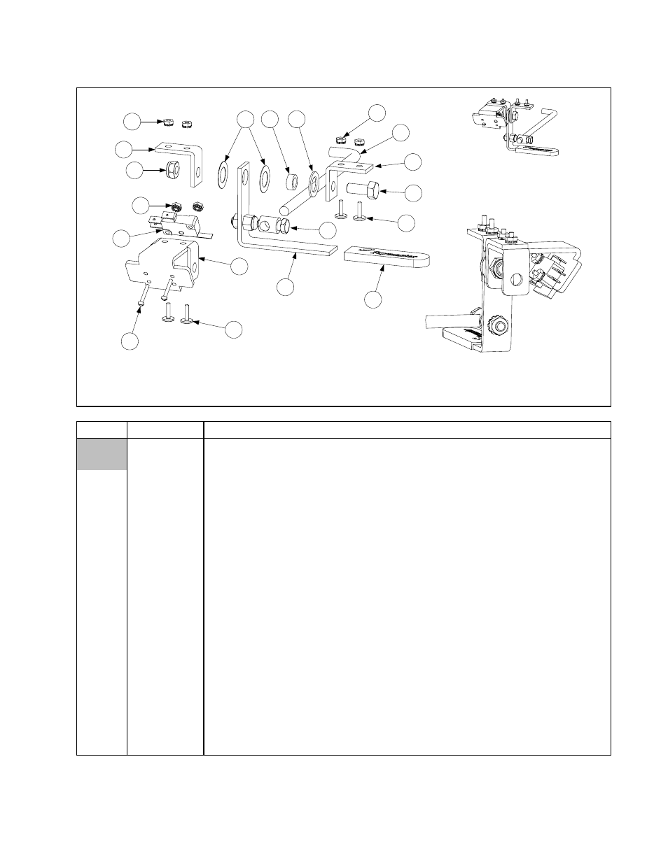
2.13.10 Oil Return Handle Assembly, Filter Magic & Standard FootPrint III
Handle and switch assembly is shown in right-hand configuration (806-3470SP). Left-hand
configuration (806-3471SP) is mirror image of 806-3470SP using same components. Oil
return valve rod (Item 16) IS NOT a component of either assembly.
Detail of Switch
Mounting
9
13
3
8
2
1
4
10
14
15
7
11
6
9
13
10
4
12
16
ITEM
PART #
COMPONENT
806-3470SP
Handle and Switch Assembly, Right (Items 1-15)
806-3471SP
Handle and Switch Assembly, Left (Items 1-15)
1
200-0821
Bracket, Handle and Microswitch
2
807-2103
Microswitch
3
809-0056
Nut, 5/16 – 24, Hex Head, Nylon Lock
4
809-0103
Screw, 8-32 x ½” Slotted Truss Head
5
809-0142
Screw, 5/16 – 24 x ¾” Hex Head
6
809-0200
Washer, Flat
7
826-1381
Washer, Nylatron (Pkg of 10)
8
826-1366
Nut, 4-40 Hex Keps (Pkg of 25)
9
809-0247
Nut, 8-32 Hex Keps
10
826-1359
Screw, 4-40 x ¾” Slot Head (Pkg of 25)
11
810-0220
Spacer, Tubular, .493 OD
12
810-0285
Swivel Fitting, Oil Return Valve Linkage
13
810-1999
Bracket, Valve Handle
14
920-0831
Handle, Oil Return
15
814-0047
Sleeve, Handle
16
910-0832
Rod, Oil Return Valve (must be ordered separately from assemblies)
*
810-0278
Valve, Ball ½-inch
*
826-1878
Kit, Brace Filter
* Not illustrated