Frymaster H50 Series User Manual
Page 129
2-66
2.18
Relays, Transformers, Wiring Assemblies and Related Parts
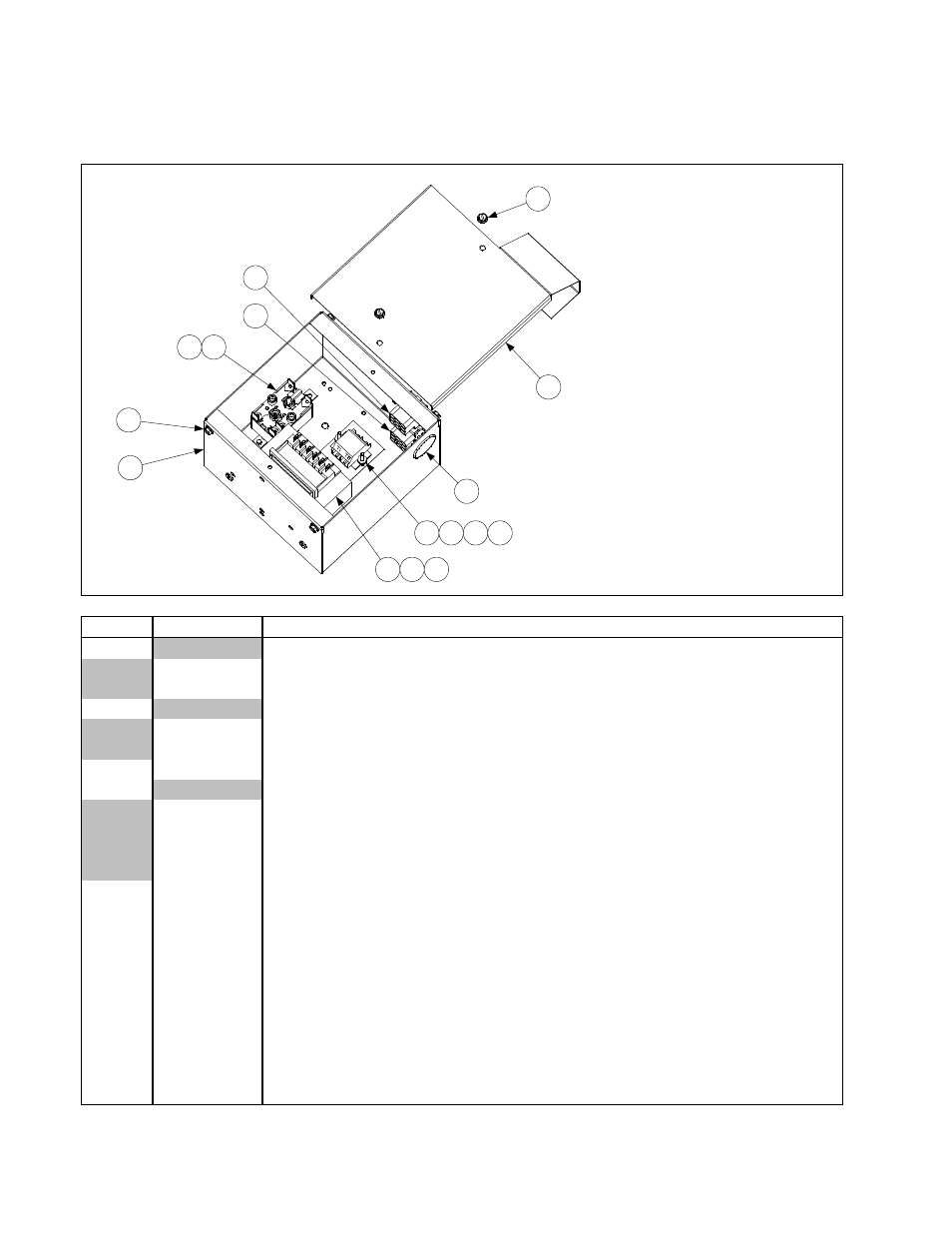
2.18.1 Filter Box Components
14
1
2
10
13
9
9
4
5
7
9
3
6
8
11
12
NOTE: The transformer (Item 4)
may differ in appearance from the
illustration depending upon the
voltage of the filter system.
NOTE: See illustrations on Page 2-69
to determine the correct plug assembly
and harness required for your specific
configuration.
Complete Assemblies:
806-8581SP 100V w/4-Terminal Relay
806-8358SP 120V w/4-Terminal Relay
806-7496SP 120V w/5-Terminal Relay
806-8582SP 208/250 w/4-Terminal Relay
For FM see 806-6209
ITEM
PART #
COMPONENT
1
Plug Assembly, Top Position
806-6725SP
4-Wires w/o keying plug (see illustration on Page 2-69)
806-8021SP
6-Wires w/keying plug in pin 5 (see illustration on Page 2-69)
2
Plug Assembly, Bottom Position
806-6719SP
5-Wires w/o keying plug in pin 6 (see illustration on Page 2-69)
806-7494SP
5-Wires w/keying plug in pin 6 (see illustration on Page 2-69)
3
807-2434
Relay, 5-Terminal Pump Motor (for 4-Terminal, use 807-0012)
4
Transformer
807-2176
100-120V Primary 12/24V Dual-Tap Secondary 50/60 Hz 50VA
807-0855
120V Primary 12V Secondary 50/60Hz, 20VA
807-0800
120V Primary 24V Secondary 50/60 Hz 50VA
807-1999
202-240V Primary 24V Secondary 50/60 Hz 50VA
5
809-0096
Screw, 6-32 x ⅝
-
inch Slot Head
6
826-1366
Nut, 4-40 Keps Hex (Pkg. of 25)
7
809-0250
Nut, 6-32 Keps Hex
8
826-1359
Screw, 4-40 x ¾-inch Slotted Pan Head (Pkg. of 25)
9
809-0360
Screw, #8 x ⅜-inch Slotted Washer Hex Head
10
810-0044
Plug, ⅝-inch
11
810-1164
Terminal Block
12
816-0217
Paper, Insulating
13
900-5250
Box, FP III Filter
14
900-5530
Cover, FP III Filter Box
*
810-1062
Harness, Filter Box
* Not illustrated