Figure 1.14 controller (sas model) – FUJITSU Disk Storage System DX60 User Manual
Page 20
Chapter 1 Components
1.1 Controller Enclosure
ETERNUS DX60 S2 Disk storage system User’s Guide -Operation-
20
Copyright 2012 FUJITSU LIMITED
P3AM-5512-03ENZ0
■
SAS model
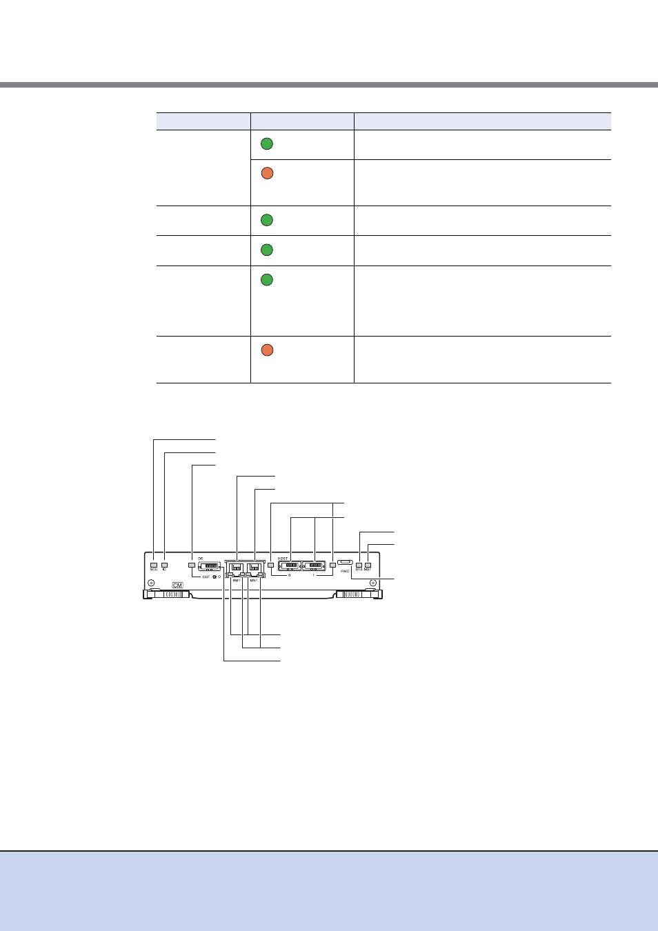
Figure 1.14 Controller (SAS model)
●
Part explanation
•
LAN (RMT) port, LAN (MNT) port
These are the RJ-45 connectors to connect LAN cables. LAN (RMT) port is not used in the
EMEA&I region.
A single controller has one LAN (RMT) port and one LAN (MNT) port.
•
SAS port (0 (left), 1 (right))
These are the miniSAS (SFF8088) connectors to connect miniSAS cables.
UNIT READY/
FAULT
(green)
The controller is in normal status.
(orange)
•
The controller is performing the initial setup after the
power is turned on.
•
The controller is in error status.
MASTER
(green)
The controller is set as a Master CM.
ACT
(green)
The controller is sending or receiving data via the LAN
port (for operation management).
LINK
(green)
•
The link between the LAN port (for operation
management) and the destination has been
established.
•
The link between the iSCSI port (host interface port)
and the destination has been established.
FAULT
(orange)
•
The controller is performing the initial setup after the
power is turned on.
•
The iSCSI port (host interface port) is in error status.
LED name
LED status
Controller status
SAS port (0 (Left), 1 (Right))
SAS (HOST) LINKUP/FAULT LED
DI (OUT) port
PWC port
ACT LED
LINK LED
MASTER LED
UNIT READY/FAULT LED
LAN (RMT) port
DI (OUT) LINKUP LED
SCU STATUS LED
IDENTIFY LED
LAN (MNT) port