4 csel setting – FUJITSU MHV2120AT User Manual
Page 55
3.4 Jumper Settings
C141-E218
3-13
3.4.4 CSEL setting
Figure 3.14 shows the cable select (CSEL) setting.
Short
Open
B
D
2
A
C
1
Note:
The CSEL setting is not depended on setting between pins Band D.
Figure 3.14 CSEL setting
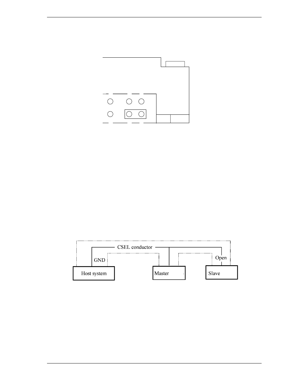
Figure 3.15 and 3.16 show examples of cable selection using unique interface
cables.
By connecting the CSEL of the master drive to the CSEL Line (conducer) of the
cable and connecting it to ground further, the CSEL is set to low level. The drive
is identified as a master drive. At this time, the CSEL of the slave drive does not
have a conductor. Thus, since the slave drive is not connected to the CSEL
conductor, the CSEL is set to high level. The drive is identified as a slave drive.
Figure 3.15 Example (1) of cable select
drive
drive