2 system configuration, 1 ata interface, 2 1 drive connection – FUJITSU MHV2120AT User Manual
Page 41
2.2 System Configuration
C141-E218
2-3
(6) Read/write circuit
The read/write circuit uses a LSI chip for the read/write preamplifier. It improves
data reliability by preventing errors caused by external noise.
(7) Controller circuit
The controller circuit consists of an LSI chip to improve reliability. The high-
speed microprocessor unit (MPU) achieves a high-performance AT controller.
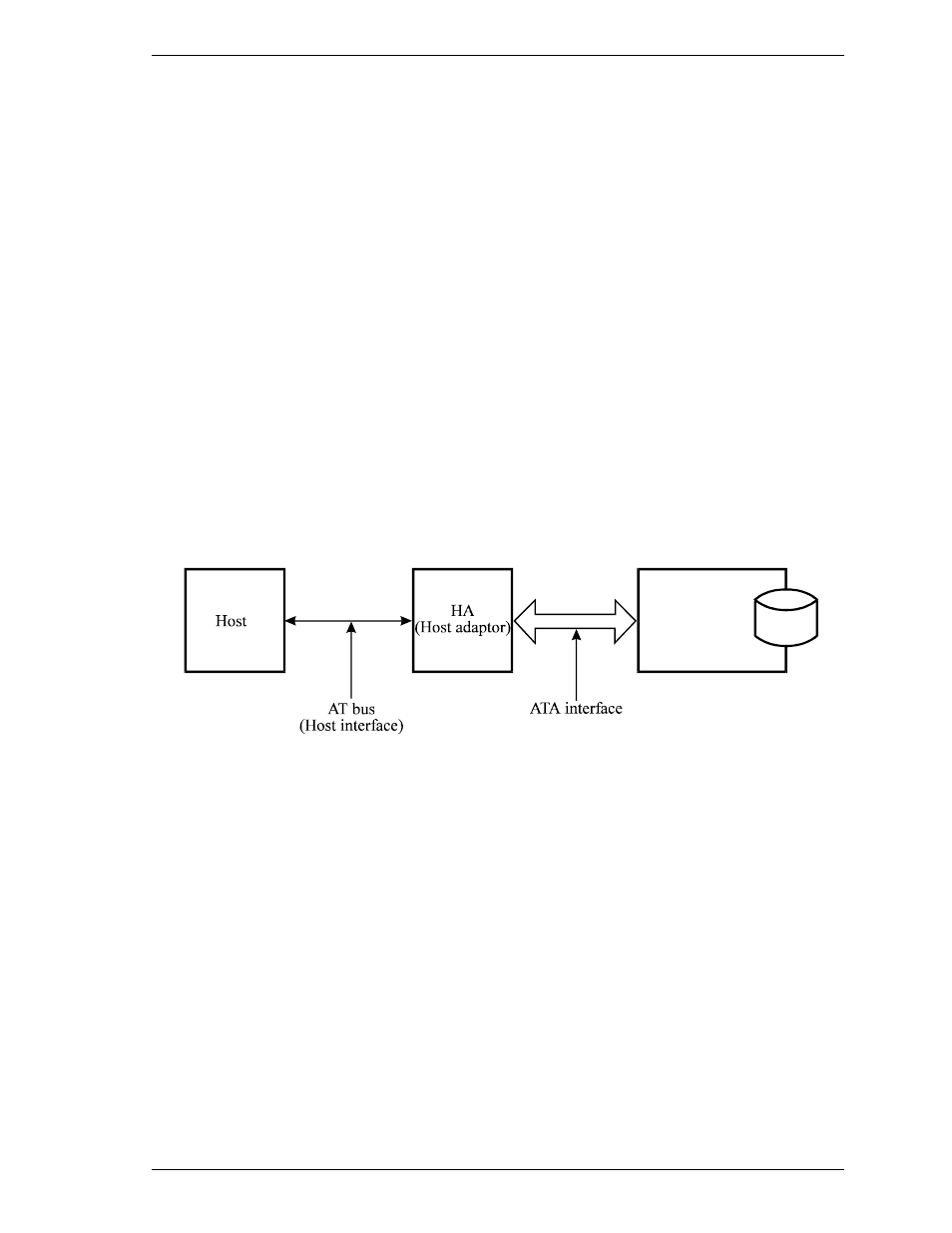
2.2 System Configuration
2.2.1 ATA interface
Figures 2.2 and 2.3 show the ATA interface system configuration. The drive has
a 44pin PC AT interface connector and supports PIO mode 4 transfer at 16.6
MB/s, Multiword DMA mode 2 transfer at 16.6 MB/s and also U-DMA mode 5
(100 MB/s).
2.2.2 1 drive connection
MHC2032AT
MHC2040AT
Figure 2.2 1 drive system configuration
MHV2120AT
MHV2100AT
MHV2080AT
MHV2060AT
MHV2040AT